Sound signal wire and process for enhancing rigidity thereof
a technology of sound signal wire and rigidity, which is applied in the direction of conductors, conductors, non-insulated conductors, etc., can solve the problems of short circuit of sound signals, serious damage, and cost ineffective process of fabricating speakers, and achieve the effect of eliminating the occurrence of roping effects and high rigidity
- Summary
- Abstract
- Description
- Claims
- Application Information
AI Technical Summary
Benefits of technology
Problems solved by technology
Method used
Image

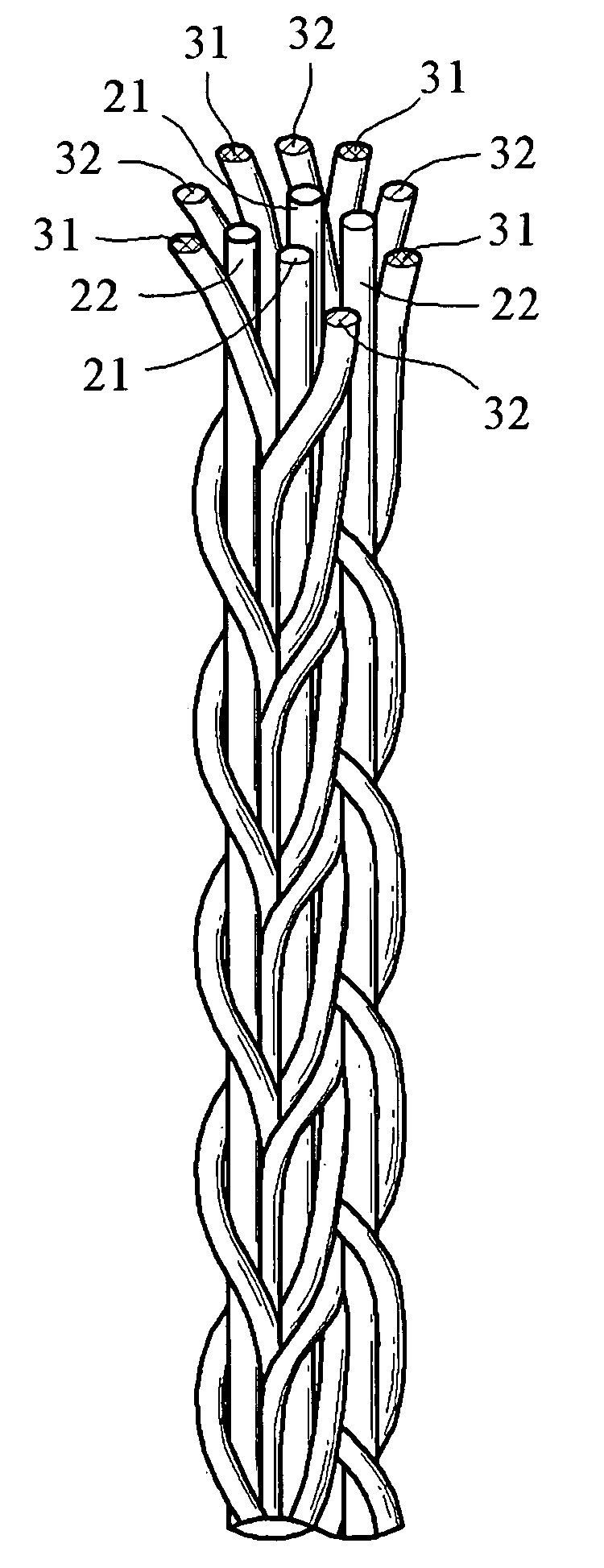
Examples
preparation of example 1
[0037]Poly meta-phendioyl meta-phenylene diamide is used as a textile material for an inner fiber. The inner fiber is made with its specification of a 40-in-2 strand (wherein the “40-in-2” means that the diameter of each of the 2 strands is 40 Ne) and encompassed by a single sheet of copper foil coated with silver to form a wire unit. Then, 7 strands of the wire units are wound and then subjected to anti-oxidation treatment at 82° C. to form Sample 1 of the sound signal wire.
preparation of example 2
[0038]The formation of Sample 2 of the sound signal wire similarly follows the above process of Preparation Example 1, except that the inner fiber is encompassed by two sheets of copper foil coated with silver to form the wire unit.
preparation of example 3
[0039]The formation of Sample 3 of the sound signal wire similarly follows the above process of Preparation Example 2, except that the inner fiber is made with its specification of a 30-in-3 strand (wherein the “30-in-3” means that the diameter of each of the 3 strands is 30 Ne).
PUM
| Property | Measurement | Unit |
|---|---|---|
| conductive | aaaaa | aaaaa |
| heat-resistant | aaaaa | aaaaa |
| plasticity | aaaaa | aaaaa |
Abstract
Description
Claims
Application Information
 - R&D
- Intellectual Property
- Life Sciences
- Materials
- Tech Scout
- Unparalleled Data Quality
- Higher Quality Content
- 60% Fewer Hallucinations
Browse by: Latest US Patents, China's latest patents, Technical Efficacy Thesaurus, Application Domain, Technology Topic, Popular Technical Reports.
© 2025 PatSnap. All rights reserved.Legal|Privacy policy|Modern Slavery Act Transparency Statement|Sitemap|About US| Contact US: help@patsnap.com