
System and method of illuminating living cells for imaging

a living cell and imaging technology, applied in the field of living cell imaging illumination, can solve the problems of increasing the probability, photobleaching, and photodamage in conventional fluorescence microscopy techniques, so as to reduce the coincidence of multiply excited electrons, minimize the rate of photobleaching and photodamage, and facilitate the reduction of both the photobleaching and the photodamage

Active Publication Date: 2006-11-28
LEICA MICROSYSTEMS CMS GMBH
View PDF5 Cites 24 Cited by
  • Summary
  • Abstract
  • Description
  • Claims
  • Application Information

AI Technical Summary

Benefits of technology

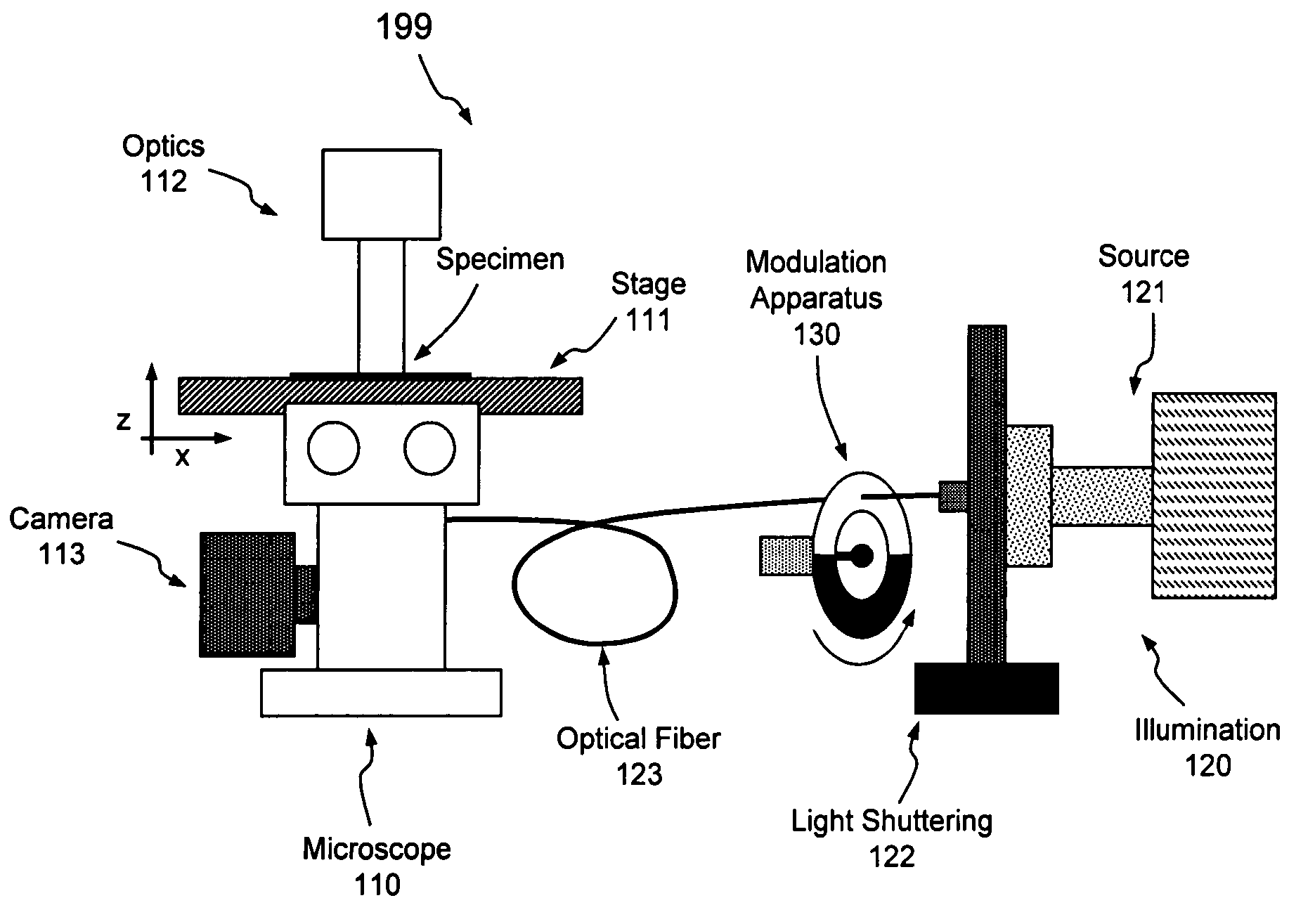
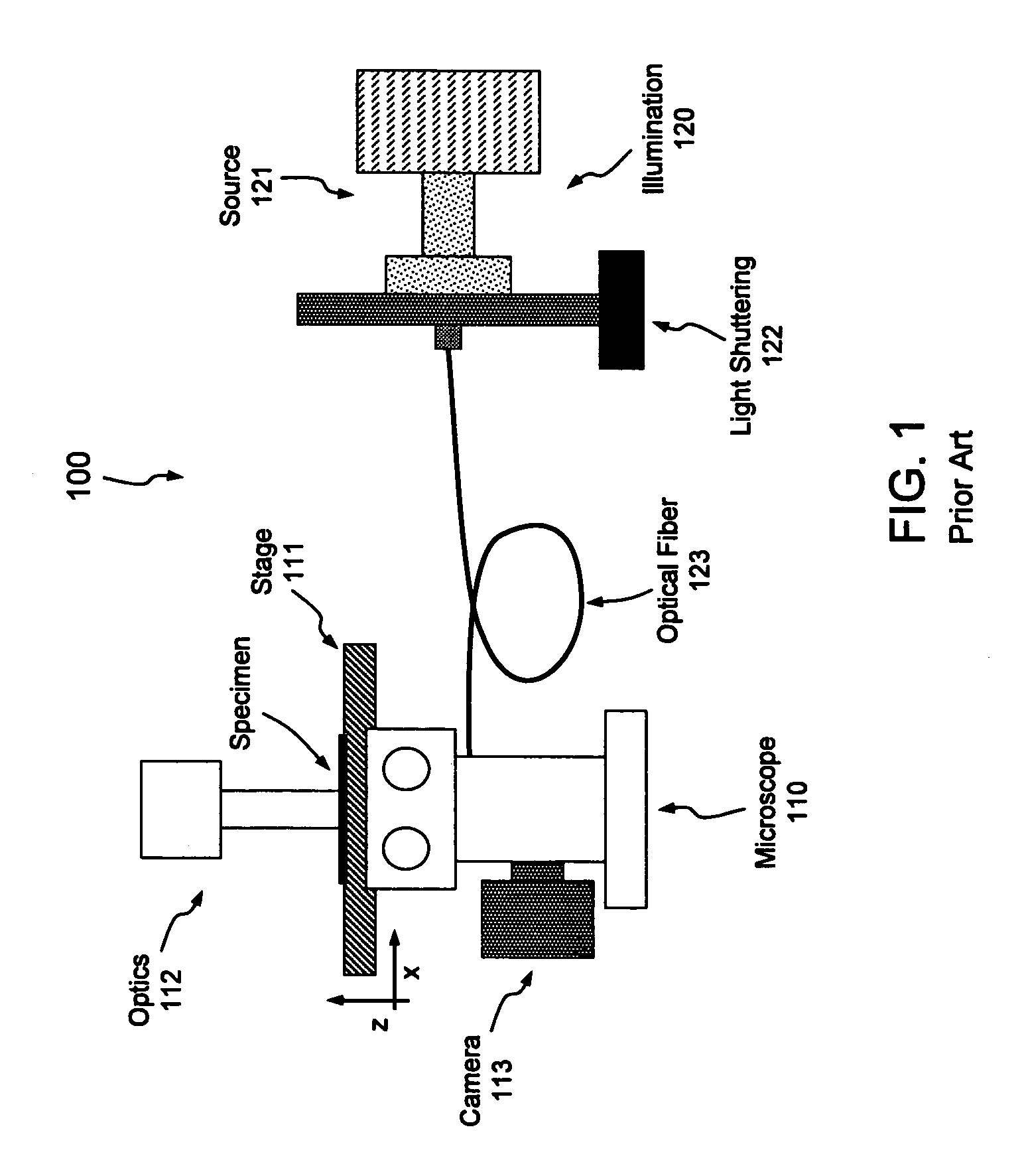
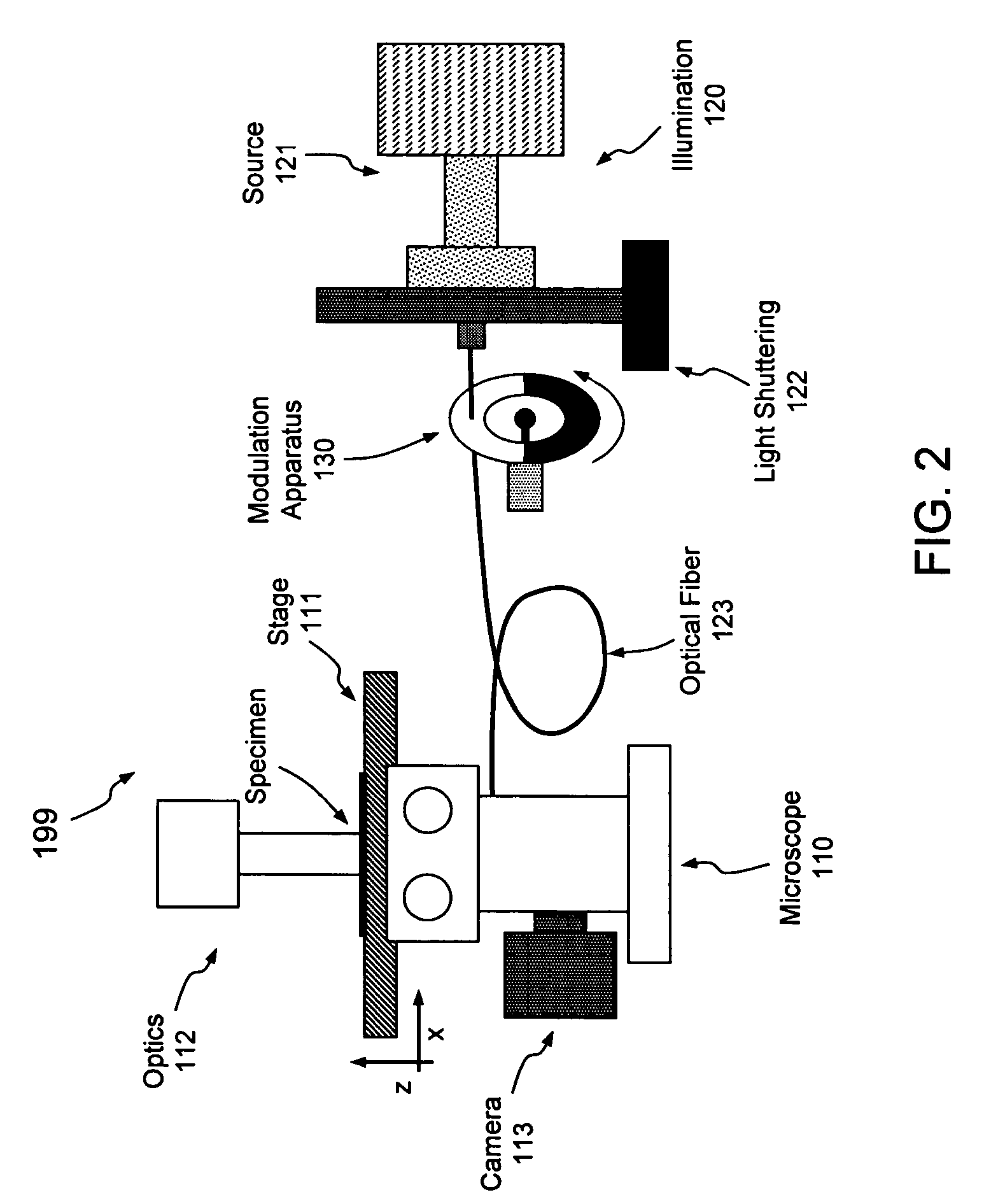
[0008]Embodiments of the present invention overcome the above-mentioned and various other shortcomings of conventional technology, providing a system and method of delivering pulsed or modulated light for illumination of a sample. Though not limited to any specific system environment or structural context, such modulated illumination may have particular utility in live-cell imaging applications where reducing the coincidence of multiply excited electrons (i.e., reducing the number of molecules in a super-excited state) may minimize the rate of photobleaching and photodamage in the molecules being studied. In that regard, aspects of the present invention may facilitate reduction of both the photobleaching and the photodamage effects induced during the process of fluorescence microscopy.

Problems solved by technology

Conventional fluorescence microscopy techniques for examining living cells suffer from at least two significant limitations: photobleaching; and photodamage.
Additionally or alternatively, such super-oxides may interact with other molecules, such as the proteins within the cell; this interaction with cellular components leads to photodamage.
Further, if a molecule is re-excited while already in the excited state (a condition referred to as “super-excited”), electrons remain in the excited state for a prolonged period of time, increasing the probability that they will interact to form super-oxides and lead to photobleaching and photodamage.

Method used


Image

  • System and method of illuminating living cells for imaging
  • System and method of illuminating living cells for imaging
  • System and method of illuminating living cells for imaging

Examples


Embodiment Construction

[0023]Aspects of the present invention pertain generally to a system and method of illumination allowing live-cell imaging with reduced photobleaching and photodamage effects. As set forth above, the longer electrons remain in the excited state, the more likely they are to form reactive chemical species such as super-oxides that lead to photobleaching and photodamage; in that regard, re-excitation of electrons that are already excited prolongs that excited state. As set forth in more detail below, if the excitation of the fluorochrome is pulsed or modulated at an appropriate frequency, however, each fluorochrome may be provided an opportunity to relax (i.e., return to the ground state and fluoresce) prior to re-excitation. The embodiments set forth below generally relate to a system and method of pulsing or otherwise modulating the intensity of illumination at a frequency operative to reduce such deleterious re-excitation of excited molecules or electrons.

[0024]Turning now to the dr...


PUM


Abstract

A system and method of providing illumination for a cell imaging system delivering modulated light for illumination of a sample. Modulation of illumination intensity may be effectuated by pulsing the output of a light source, for example, or by selectively interrupting light provided by the source. Such modulated illumination may have particular utility in applications where reducing the number of electrons in a super-excited state may minimize the rate of photobleaching and photodamage in the molecules being studied.

Description

CROSS-REFERENCE TO RELATED APPLICATIONS [0001]The present application claims the benefit of U.S. provisional application Ser. No. 60 / 436,776, filed Dec. 26, 2002, entitled “SYSTEM AND METHOD OF ILLUMINATING LIVING CELLS FOR IMAGING.”FIELD OF THE INVENTION [0002]Aspects of the present invention relate generally to illuminating living cells for imaging, and more particularly to a system and method of providing modulated illumination intensities in fluorescence microscopy applications.DESCRIPTION OF THE RELATED ART [0003]Fluorescence microscopy is well described in the art and is commonly used for the examination of biological materials. Fluorescence microscopy has also been used to examine living cells since at least the 1960's. More recently, researchers have demonstrated that Green Fluorescent Protein (GFP) can be expressed in eukaryotic cells, that GFP can form chimeric proteins in these cells, and that the GFP assembled in eukaryotic cells retains its fluorescence. Numerous peer-r...

Claims


Application Information

Patent Timeline
IPC IPC(8): G01J1/58G01N21/64G02B21/16
CPCG01N21/6458G02B21/16
Inventor GOODWIN, PAUL C.
Owner LEICA MICROSYSTEMS CMS GMBH
Learn More