Detectable warning system

a detection and warning system technology, applied in wireless systems/telephones, ways, instruments, etc., can solve the problems of difficult installation of warnings, difficulty in discerning the boundary between pedestrian safety and danger, and inconvenient installation of such warnings

Active Publication Date: 2006-11-28
GRAYSON THOMAS
View PDF1 Cites 24 Cited by
  • Summary
  • Abstract
  • Description
  • Claims
  • Application Information

AI Technical Summary

Benefits of technology

[0009]It is an object of the invention to provide a system for allowing the effective installation of detectable warnings upon a pavement surface using heat, wherein the warning domes are not harmed during application to said pavement surface. Accordingly, the detectable warnings are made of a heat resistant casting material that is joined to a layer of thermoplastic. The thermoplastic allows the warnings to be effectively mounted and evenly distributed on the pavement surface.
[0010]It is another object of the invention to provide a system for allowing the easy fabrication of detectable warning dome carriers for quick and easy subsequent installation of a plurality of domes simultaneously. Accordingly, by a first embodiment, a mold is used to initially create a top layer of thermoplastic material and create the detectable warning domes thereupon. Upon removal from the mold, the detectable warning dome carriers may be easily adhered to pavement surfaces by the application of heat. In particular, the thermoplastic top layer drapes over the domes and adheres to the pavement surface. The domes themselves also rest upon the pavement surface but are held thereagainst by the top layer. Further, by a second embodiment, a mold is used to initially create the detectable warning domes, and then create a base layer thereupon within which the warning domes are adhered and partially submerged. The base layer is adhered to the pavement surface and secures the domes thereonto.

Problems solved by technology

When raised curbs do not mark and separate the pedestrian route on a sidewalk from the vehicular way, as at curb ramps, vehicle drop-offs, or depressed corners at intersections, it is difficult for some pedestrians to discern the boundary between pedestrian safety and hazard.
Further, the installation of such warnings is not readily compatible with standard paving techniques.
Unfortunately, the use of thermoplastic warning domes makes the system extremely difficult to install, since heat must be used to install the sheets, but heat will deform or destroy the thermoplastic domes.

Method used


Image

  • Detectable warning system
  • Detectable warning system
  • Detectable warning system

Examples


first embodiment

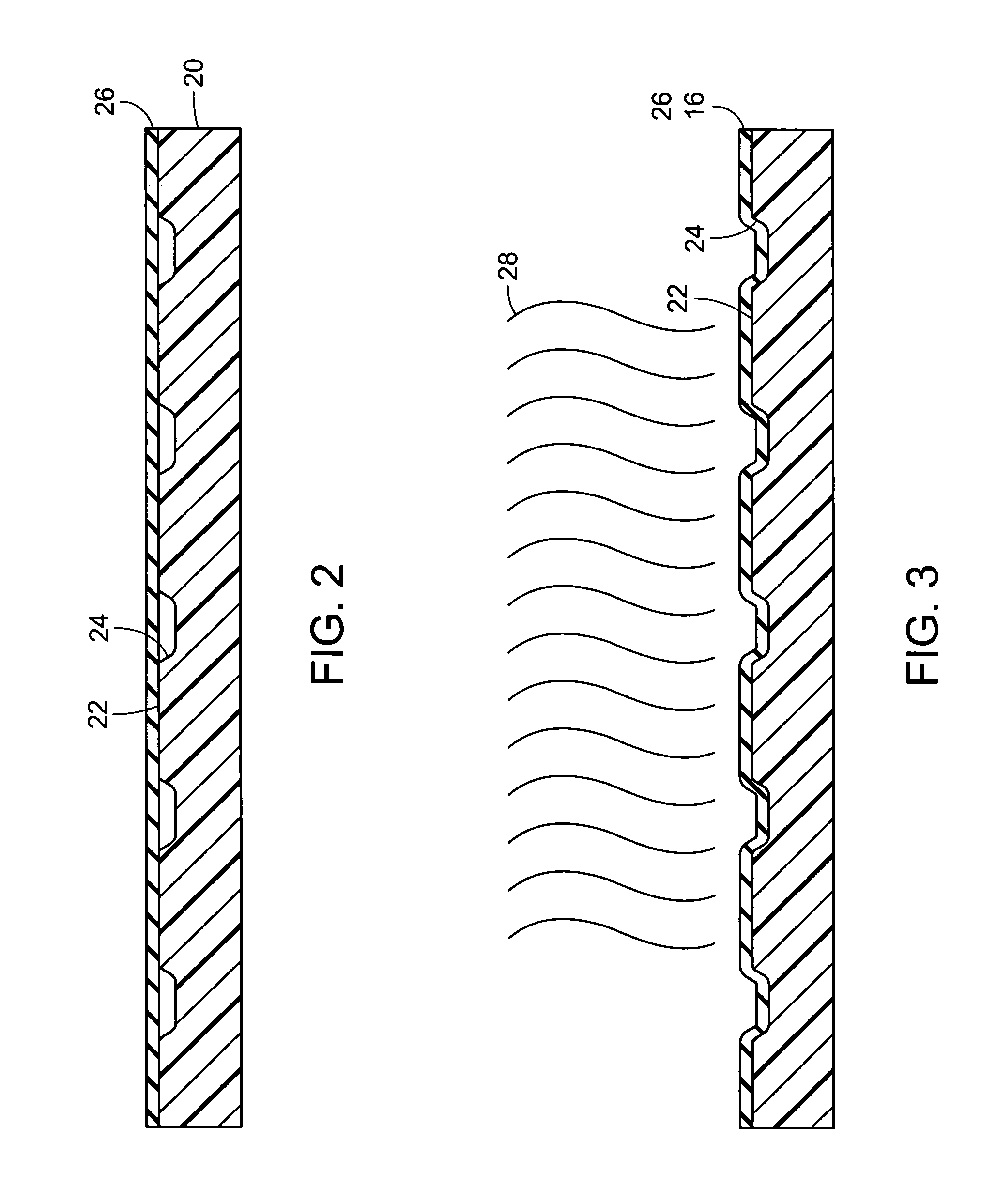
[0028]Referring to FIG. 2, formation of the detectable warning carrier assembly centers upon a mold 20 having a top surface 22 and a plurality of dome forming cavities 24 extending downwardly from the top surface 22. The dome forming cavities 24 are shaped like inverted truncated warning domes and are spaced apart as required by regulations such as ADAAG 4.29.2, and to otherwise function as an effective detectable warning. The dome forming cavities 24 are dimensionally modified to accommodate a coating of thermoplastic as will be apparent hereinafter.

[0029]A first sheet of thermoplastic 26 is illustrated extending across the top surface 22, spanning the mold 20, and thereby extending across all dome forming cavities 24. The first sheet of thermoplastic 26 may actually be numerous sheets of thermoplastic that are adjacent and / or overlap each other so that they together substantially span the top surface 22 of the mold 20.

[0030]Referring now to FIG. 3, heat 28 is applied to the thermo...

second embodiment

[0037]Formation of the second embodiment is illustrated in FIGS. 7 thru 9. In FIG. 7, the heat resistant casting material 30 has been added directly into the mold to partially fill the dome forming cavities 24 of the mold 20. In particular, the heat resistant casting material 30 is added until it substantially reaches the top surface 22 of the mold 20. What will become the dome base surfaces 12A are shown as uneven in an exaggerated sense to emphasize the flowability of the casting material. The dome base surfaces 12A are still, in fact, preferably somewhat uneven to facilitate secure attachment to the base layer 14 as will be illustrated hereinafter.

[0038]In FIG. 8 a second sheet of thermoplastic material 32 has been overlaid upon the mold, spanning the top surface thereof, to coat the detectable warning domes 12 and with a continuous piece of thermoplastic material to form the base layer 14. In particular, the second sheet of thermoplastic material 32 spans the mold 20, covers all...


PUM


Abstract

A detectable warning system, for tactily signaling the presence of a terrain transition to a pedestrian, using a plurality of detectable warning domes that are arranged in a grid within a detectable warning carrier assembly. The detectable warning carrier assembly comprises a carrier layer being one of a top layer and a base layer of thermoplastic material with heat resistant detectable warning domes therebetween. The carrier layer is heated and adhered to a pavement surface. The detectable warning domes protrude from the pavement surface in an evenly spaced pattern that is detectable by the pedestrian using a cane or other guidance instrument.

Description

CROSS REFERENCES AND RELATED SUBJECT MATTER[0001]This application is a continuation-in-part of patent application Ser. No. 10 / 716,155, filed in the United States Patent Office on Nov. 18, 2003 now U.S. Pat. No. 6,960,989.BACKGROUND OF THE INVENTION[0002]The invention relates to a detectable warning system. More particularly, the invention relates to a system for easily and effectively applying prefabricated detectable warnings to pavement to provide a tactile warning to pedestrians regarding a hazardous transition.[0003]It is well known that persons with little or no usable vision depend upon environmental cues—ambient sounds, edges and other physical elements that can be sensed by a cane, and texture changes underfoot—for safe and independent travel. People with low vision can also use color contrast as a navigation aid. When raised curbs do not mark and separate the pedestrian route on a sidewalk from the vehicular way, as at curb ramps, vehicle drop-offs, or depressed corners at ...

Claims


Application Information

Patent Timeline
Patent Type & Authority Patents(United States)
IPC IPC(8): H04B3/36G08G1/095A61H3/06E01C11/22G08G1/005G09B21/00
CPCA61H3/066E01C11/222G08G1/005G09B21/003H04B2203/5412H04B2203/5441
Inventor GRAYSON, THOMAS
Owner GRAYSON THOMAS
Why Eureka
Try Eureka