Image coding device and coding method of same

a coding device and image technology, applied in the field of image coding device and coding method of same, can solve the problems of flicker noise, deterioration of image quality, and markable deterioration of image quality, and achieve the effect of reducing the flicker noise of coded images

Inactive Publication Date: 2006-11-28
SONY CORP
View PDF10 Cites 27 Cited by
  • Summary
  • Abstract
  • Description
  • Claims
  • Application Information

AI Technical Summary

Benefits of technology

[0007]An object of the present invention is to provide an image coding device, and a coding method thereof, able to reduce the flicker noise of coded images when compressing and coding moving images in accordance with the Motion JPEG-2000 standard.

Problems solved by technology

With moving images, however, there is the problem of a remarkable deterioration in the image quality.
Considered a particular problem in the deterioration of the image quality is the flicker noise caused by the occurrence of noise at random positions in a succession of frames.
Despite this, for some reason, noise at the time of taking the picture with a camera etc. will cause noise in the image.

Method used


Image

  • Image coding device and coding method of same
  • Image coding device and coding method of same
  • Image coding device and coding method of same

Examples


first embodiment

[0037

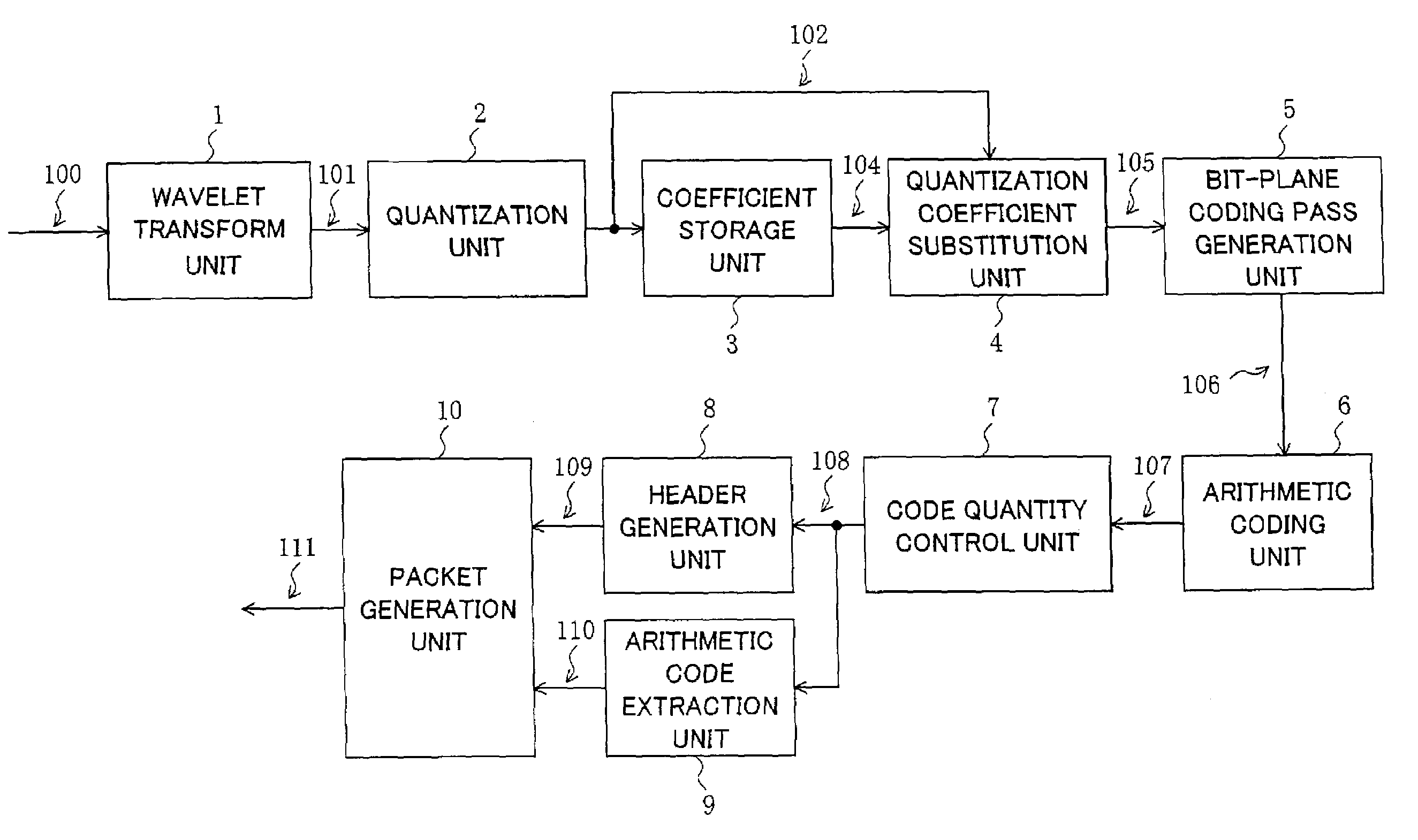
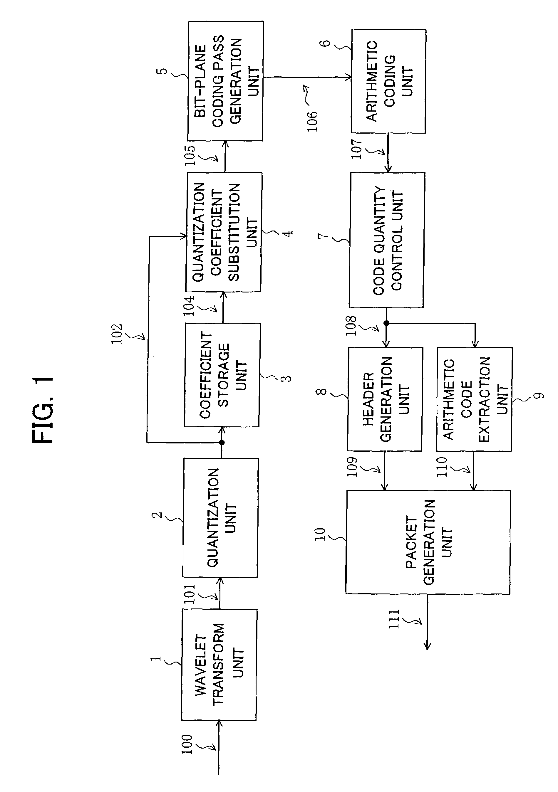
[0038]FIG. 1 is a block diagram of an image coding device according to a first embodiment of the present invention.

[0039]As illustrated, the image coding device of the present embodiment includes a wavelet transform unit 1, a quantization unit 2, a coefficient storage unit 3, a quantization coefficient substitution unit 4, a bit-plane coding pass generation unit 5, an arithmetic coding unit 6, a code quantity control unit 7, a header generation unit 8, an arithmetic code extraction unit 9, and a packet generation unit 10.

[0040]Next, the components of the image coding device of the present embodiment will be explained.

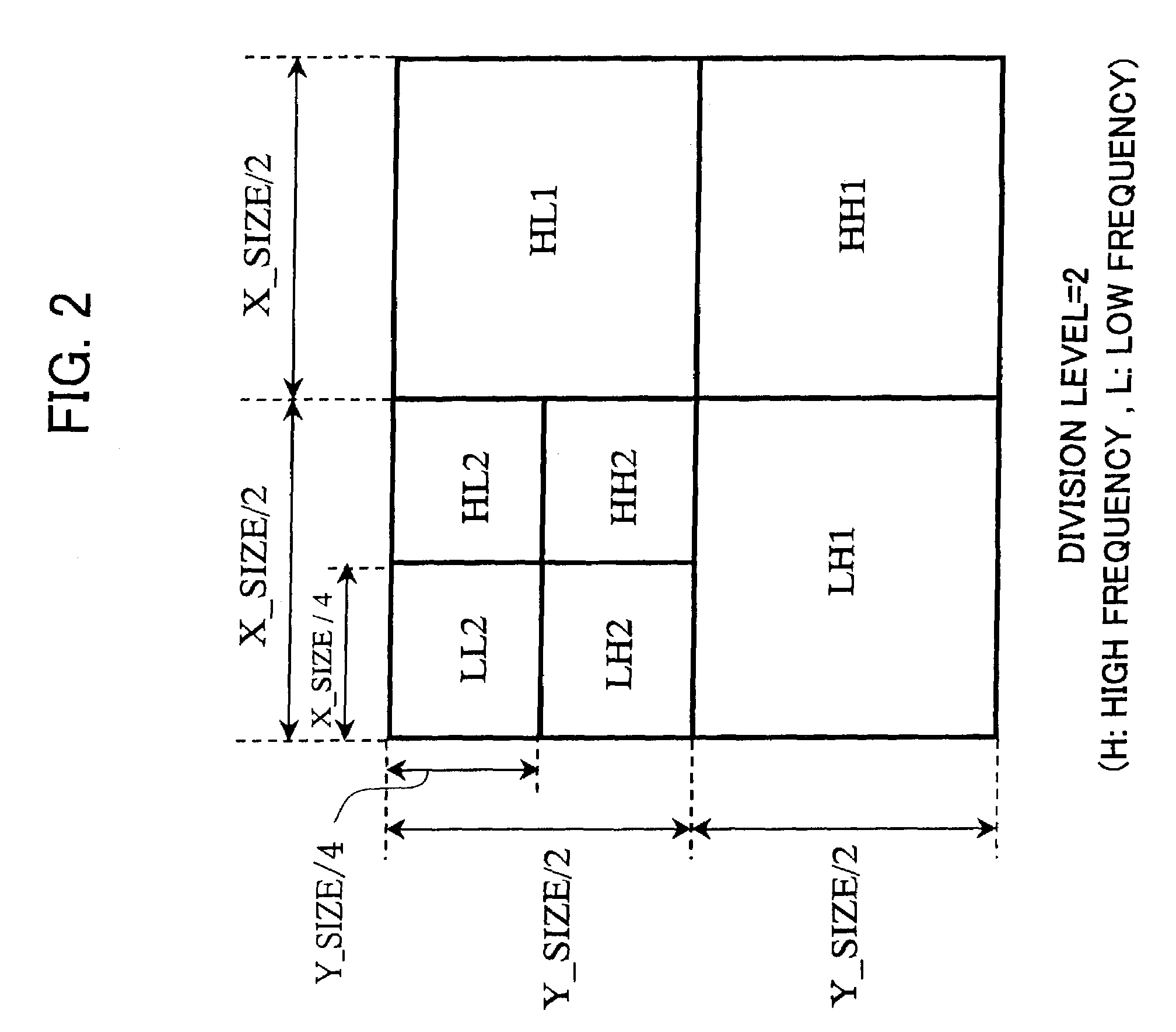
[0041]The wavelet transform unit 1 applies a wavelet transform to the input image signal 100. A wavelet transform is generally accomplished by a filter bank comprised by low-pass filters and high-pass filters. Therefore, since digital filters for wavelet transform generally have an in-pulse response (filter coefficients) of a plurality of tap lengths, it is necessa...

second embodiment

[0086

[0087]FIG. 9 is a block diagram of an image coding device according to a second embodiment of the present invention.

[0088]As illustrated, the image coding device of the present invention has substantially the same configuration as the image coding device of the first embodiment shown in FIG. 1. However, in the image coding device of the first embodiment shown in FIG. 1, the coefficient storage unit 3 only stored the quantization coefficients 102 output from the quantization unit 2. In the image coding device of the present embodiment, a coefficient storage unit 3A stores not only quantization coefficients 102 output from the quantization unit 2, but also wavelet transform coefficients 101 output from a wavelet transform unit 1.

[0089]As shown in FIG. 9, the wavelet transform coefficients 101 generated by the wavelet transform unit 1 are supplied to the quantization unit 2, the coefficient storage unit 3A, and a quantization coefficient substitution unit 4A.

[0090]The quantization...


PUM


Abstract

An image coding device for reducing flicker noise in moving image coding based on Motion JPEG-2000, which applies wavelet transform to an input image, quantizes the wavelet transform coefficients, and replaces quantization coefficients of adjacent frames in accordance with a predetermined judgment condition. The device spreads the finally output quantization coefficients into bit-planes from the MSB to LSB, generates coding passes in each bit-plane, performs arithmetic coding in the coding passes, controls the code quantity to a target code quantity from the generated arithmetic codes, and generates a packet of the image data by attaching a header to the arithmetic codes. The quantization coefficients are replaced based on a difference of absolute values of the quantization coefficients at the same sub-band in the adjacent frames. By further adding the wavelet transform coefficients, erroneous detection in the substitution processing can be decreased and the flicker noise can be suppressed effectively. Also, an image coding method for the same.

Description

BACKGROUND OF THE INVENTION[0001]1. Field of the Invention[0002]The present invention relates to a coding device of moving images based on Motion JPEG-2000, the motion version of the still picture coding standard JPEG-2000, and a coding method of the same.[0003]2. Description of the Related Art[0004]The next generation still picture coding standard JPEG-2000, for which standardization work was completed in January 2001 by the ISO / IEC (International Organization for Standardization / International Electrotechnical Commission), has abundant functions such as a superior compression performance and also scalability, progressiveness, error tolerance, and reversible compression. Thus, it is expected to be widely used in the next generation of digital still cameras, printers, scanners, etc. On the other hand, the motion version of the JPEG-2000, that is, Motion JPEG-2000, inherits the superior features of the JPEG-2000 intact and is expected to find use in future camcoders, monitor cameras, ...

Claims


Application Information

Patent Timeline
Patent Type & Authority Patents(United States)
IPC IPC(8): G06K9/36H04N19/60G06F17/14H03M7/30H03M7/40H04N19/102H04N19/154H04N19/18H04N19/196H04N19/423H04N19/63H04N19/80H04N19/85H04N19/91
CPCG06F17/148
Inventor FUKUHARA, TAKAHIROKIMURA, SEIJIARAKI, JUNYA
Owner SONY CORP
Why Eureka
Try Eureka