Image reconstruction method

a reconstruction method and image technology, applied in the field of scanning probe microscopes, to achieve the effect of improving the repeatability and accuracy of the reconstructed image surface, improving the visual rendering of the reconstructed surface, and easy analysis and correction of inconsistent image data

Inactive Publication Date: 2006-11-28
BRUKER NANO INC
View PDF2 Cites 23 Cited by
  • Summary
  • Abstract
  • Description
  • Claims
  • Application Information

AI Technical Summary

Benefits of technology

[0024]The preferred embodiment overcomes the drawbacks of slope-based image reconstruction systems by providing a method of post-filtering re-constructed data points that more easily analyzes and corrects inconsistent image data obtained with a scanning probe microscope tip in an efficient manner that improves the visual rendering of the reconstructed surface and improves both repeatability and accuracy of the reconstructed image surface.
[0025]According to a preferred embodiment, a method of slope-based image reconstruction of a re-entrant surface topology employing a scanning probe microscope is provided. The method generates a slope based reconstructed image using the data obtained by a tip of the scanning probe microscope. The data is indicative of, for example, a characteristic of a re-entrant surface topology of a sample. The step of generating a slope-based reconstructed image includes calculating a slope and an indication of a direction of the slope of the image at a particular region and determines, using the slope and the indication of direction, a probe contact point between the tip and the sample at that region. The method further includes the steps of applying a geometric shape filter configured to eliminate reconstructed image data that are not consistent with a tip shape of the probe used to capture the image; and applying a median filter configured to reduce artifacts in the reconstructed data. The step of applying the median filter is preferably conducted to reconstruct vectors during extraction vector selection based on known tip shape parameters.
[0026]Overall, the method of image reconstruction in accordance with the present invention enhances a reconstructed image by reducing noise and artifacts associated with noise in the original image data. Thereby, less filtering is required of the original image data and, in some cases, post-processing of the “reconstructed” image data may not be necessary. The invention is also particularly directed to alternative methods to the slope-base method that provide the capability to reconstruct a re-entrant sample surface.

Problems solved by technology

Notwithstanding the fact that scanning probe microscopes are high resolution instruments, the ultimate resolution of the data obtained by such probe-based instruments is limited by the physical characteristics of the tip of the probe itself.
More particularly, there are limitations as to how small, and sharp, the tip can be made.
In view of this, the tip shape is reflected in the acquired data, a problem that is exacerbated by the fact that AFMs often image very small (e.g., Angstrom scale) features.
As a result, an error in the acquired data results and the corresponding accuracy of the surface image is significantly compromised.
However, for many applications, the degree of accuracy required to resolve the features of the sample surface is significantly greater, such that tip shape error is unacceptable.
With typical tip widths in the range of about 70 nm, the tip shape clearly introduces significant error in the data and must be removed to accurately image the sample surface.
Moreover, the aforementioned problems can be exacerbated by the fact that complex sample surface topologies require a commensurate increase in tip shape complexity to image such surfaces.
However, with the increase in tip shape complexity, there typically is a corresponding increase in error in the AFM data.
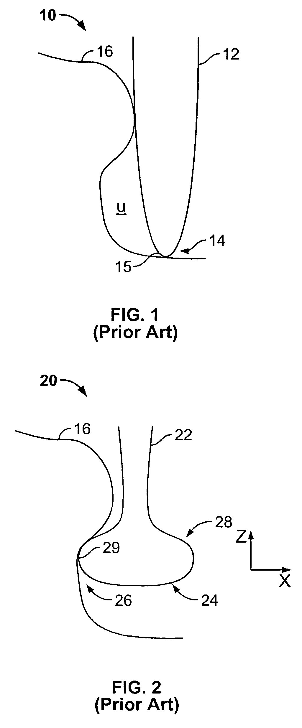
Importantly, this acquired image may not accurately reflect sample surface characteristics due to, among other things, the error introduced by the shape of the pointed tip.
In addition to introducing at least some tip shape error in the acquired data, probe tip 10 is unable to image certain surfaces.
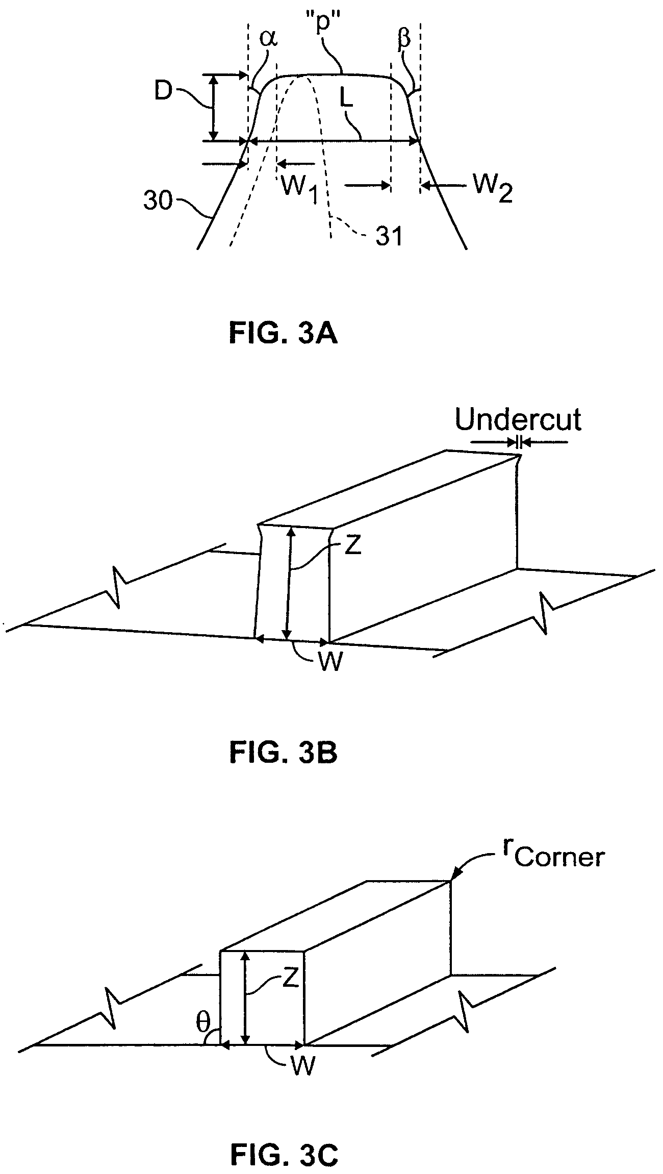
In particular, although suitable for many applications, based on its shape probe tip 10 is simply unable to accurately depict vertical sidewalls and undercut regions (which often exist in semiconductor fabrication, for example) in the corresponding sample surface topography.
Notably, this is due to limitations in both the tip shape and the algorithms used to control tip position.
However, with this increase in flexibility of the types of samples that can be imaged, correcting and reconstructing the image data becomes increasingly difficult.
Although solutions have been attempted with some success for conventional AFMs, extracting tip shape errors from CD AFM data has been an inexact process.
Moreover, as features become smaller, and because the tip is at least somewhat limited in just how small it can be made, the convolution of the tip in the image data becomes more substantial, and thus it is becoming increasingly important that the tip shape be removed for accurate measurements.
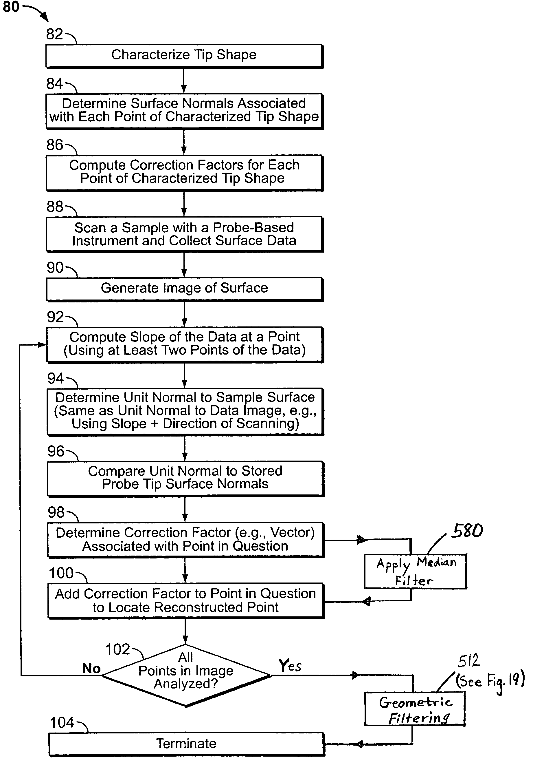
First, by simply subtracting the tip width from the image data, it is assumed that the tip-sample contact is being made at a particular point, for example, at the vertical tangent of the protuberances of the boot shaped or CD tip (i.e., at point 29, FIG. 2). However, as the tip scans along a particular topography, the contact point of the tip on the sample translates along the surface of the tip and thus the effective width of the tip at the contact point changes. As a result, a single-valued tip width subtraction is inexact. By simply subtracting off a single value tip-width, an error remains in the reconstructed image as each feature of a unique tip shape cannot be fully accounted for in correcting AFM image data. These errors are directed to inaccuracies in the image of the sample surface shape for both topology and CD width measurements at a particular height. Another significant drawback is that the width defined in Equations 2 and 3 set forth above are merely estimates for the actual tip width. As the samples to be imaged continue to demand greater resolution, these equations will become inadequate even for those applications where tip-width correction provides an acceptable correction.
A drawback of slope-matching, or “slope-based,” reconstruction methods is that Legendre transforms used in the analysis, which require numerical derivatives of the data, can be highly sensitive to noise in the original image data.
However, due to inherent limitations, the use of median filters alone does not solve the problem of noise amplification and artifact generation in the reconstructed image.
Certain known techniques to smooth or reduce noise can also eliminate crucial features in an image, thereby causing false image reconstruction.

Method used


Image

  • Image reconstruction method
  • Image reconstruction method
  • Image reconstruction method

Examples


Embodiment Construction

[0071]The preferred embodiments are directed toward improved methods of correcting reconstructed image data obtained with a scanning probe microscope by accurately accounting for probe tip shape in reconstructing the image of the sample surface. More particularly, the preferred method determines the actual point of contact of the probe tip on the sample surface for several points in a dilated image profile, corrects inconsistent image data with the tip shape used to capture the image data that improves the visual rendering of the reconstructed surface and improves both repeatability and accuracy of the reconstructed image surface. The present embodiment also provides alternate methods of image reconstruction.

Image Correction Using Point of Tip Contact Determination

[0072]Turning initially to FIG. 4A–4C, a sample 50 to be scanned by an AFM, as well as the resulting “raw” or dilated image data 54, are shown schematically together with the desired corrected image data 56. In particular,...


PUM


Abstract

A method of extracting the shape of a probe tip of a probe-based instrument from data obtained by the instrument is provided. The method employs algorithms based on the principle that no reconstructed image points can physically occupy the same region as the tip during imaging. Sequential translates of the tip shape or volume sweep out an area or volume that is an “exclusion zone” similar to morphological erosion. The embodiments of the alternative method use either the region defined by the tip boundary or simply the tip boundary.

Description

RELATED PATENT APPLICATIONS[0001]The present application is a continuation-in-part (CIP) of U.S. patent application Ser. No. 10 / 139,949 filed May 6, 2002, now U.S. Pat. No. 6,810,354, and hereby incorporated by reference herein.BACKGROUND OF THE INVENTION[0002]1. Field of the Invention[0003]The present invention is directed to scanning probe microscopes (SPMs), and more particularly, to alternate methods of accounting for the shape of the probe tip in the acquired image, the methods being particularly adapted for measuring critical dimensions (CD) and features of semiconductor wafers, data recording media, and related.[0004]2. Description of Related Art[0005]Several known probe-based instruments monitor the interaction between a cantilever-based probe and a sample to obtain information concerning one or more characteristics of the sample. For example, SPMs, such as the atomic force microscope (AFM), are devices which typically use a sharp tip and low forces to characterize the surfa...

Claims


Application Information

Patent Timeline
Patent Type & Authority Patents(United States)
IPC IPC(8): G01B15/04G01B3/22G01Q30/04G01Q30/06G01Q60/00G01Q70/10
CPCB82Y35/00G01Q30/06G01Q40/00
Inventor DAHLEN, GREGORY A.FOREMAN, WILLIAM
Owner BRUKER NANO INC
Why Eureka
Try Eureka