Pipe-inspection system

a technology of inspection system and pipe, applied in the direction of diagnostic recording/measuring, instruments, mechanical equipment, etc., can solve the problems of pipeline failure, pipeline flaws, lost services and revenues, etc., to reduce friction within the pipeline, avoid damage, and negotiate bends and junctions. , the effect of reducing friction

Inactive Publication Date: 2006-12-05
ARIZONA PUBLIC SERVICE
View PDF51 Cites 70 Cited by
  • Summary
  • Abstract
  • Description
  • Claims
  • Application Information

AI Technical Summary

Benefits of technology

[0017]Accordingly, it is an advantage of the present invention that a pipe-inspection system is provided.
[0018]It is another advantage of the present invention that a pipe-inspection system is provided that is compatible with eddy-current and other non-destructive examination techniques for inspection of a metallic pipeline.
[0019]It is another advantage of the present invention that a pipe-inspection system is provided that is configured to easily negotiate bends, junctions, and obstacles within the pipeline.
[0020]It is another advantage of the present invention that a pipe-inspection system is provided that is sanitary, non-contaminating, and non-damaging.
[0021]It is another advantage of the present invention that a pipe-inspection system is provided that is lightweight and fabricated of materials selected to reduce friction within the pipeline.
[0022]The above and other advantages of the present invention are carried out in one form a pipe-inspection system for the inspection of a pipeline. The system includes a plurality of wheeled guidance units, a transmission unit coupled between first and second ones of the wheeled guidance units, a reception unit coupled between second and third ones of the wheeled guidance units, a lead line coupled to the first wheeled guidance unit, and a trail line coupled to the fourth guidance unit.

Problems solved by technology

Pipelines develop flaws over time.
If left uncorrected, such flaws may eventually result in catastrophic failure of the pipeline.
Such a catastrophic failure may result in lost services and revenues.
Analysis of these distortions locates and defines flaws in the pipeline.
The mechanics of passing an inspection system present several problems.
A problem exists in that many inspection systems contain components that are unable to negotiate sharp bends or junctions.
These systems are therefore unsuitable for use with convoluted pipelines.
In addition, an inspection system that is unable to negotiate the bends and junctions in a pipeline is likely to become jammed in the pipeline.
If a system becomes stuck within a pipeline, then the system itself becomes a “flaw” (i.e., a blockage) of the pipeline, necessitating repair.
Systems configured to move in only one direction are therefore undesirable.
Such systems may therefore be carriers of disease and parasites, and are therefore unsuitable where sanitary conditions must be maintained, as in a municipal water system or a food-processing facility.
Similarly, many inspection systems contain materials that pose a risk of contamination.
For example, lubricants or materials that corrode or shed are inherently unsuitable for pipelines used in municipal water systems, or food- or chemical-processing facilities.
Conversely, many inspection systems contain materials that may be adversely affected by the normal-contents of the pipeline, i.e., the normal contents of the pipeline may corrode or degrade the materials of the system.
A system with steel components, for example, would be entirely unsuitable for a pipeline that normally carries sulfuric acid.
Also, many inspection systems contain components, such as pull lines or housings, that may potentially damage the pipeline.
For example, steel housings may scratch the inside of the pipeline, thereby producing potential future flaws.
An inspection system is limited in the length of pipeline inspected in one pass by its ability to move through the pipeline.
Heavy systems generate more friction than similar lightweight systems.
Cumbersome systems containing large components negotiate bends and junctions less readily than more streamlined systems with smaller components.
Such cumbersome systems are therefore undesirable.
The material of which a system is made may have a severe effect upon the generated friction.
Systems made of materials that exhibit a high frictional constant are therefore undesirable.
For inspection systems that are pulled through a pipeline by a towline, the towline may produce a significant amount of friction in and of itself.
For example, it takes considerable force to simply drag a half-inch steel cable through a two-kilometer steel pipeline.
In addition, the cable poses a significant hazard to the pipeline, especially at bends and junctions where the dragging of the cable may actually cut into the inner surface of the pipeline.
The umbilical line itself may generate significant friction.

Method used


Image

  • Pipe-inspection system
  • Pipe-inspection system
  • Pipe-inspection system

Examples


Embodiment Construction

[0051]Throughout this discussion, items are assigned three- or four-digit reference numbers whose first digit (if three-digit) or first two digits (if four digit) reflect the Figure in which the item first appears. That is, items first appearing in FIG. 1 are assigned reference numbers between 100 and 199, etc. Once assigned, a given reference number is used in all Figures in which that item appears.

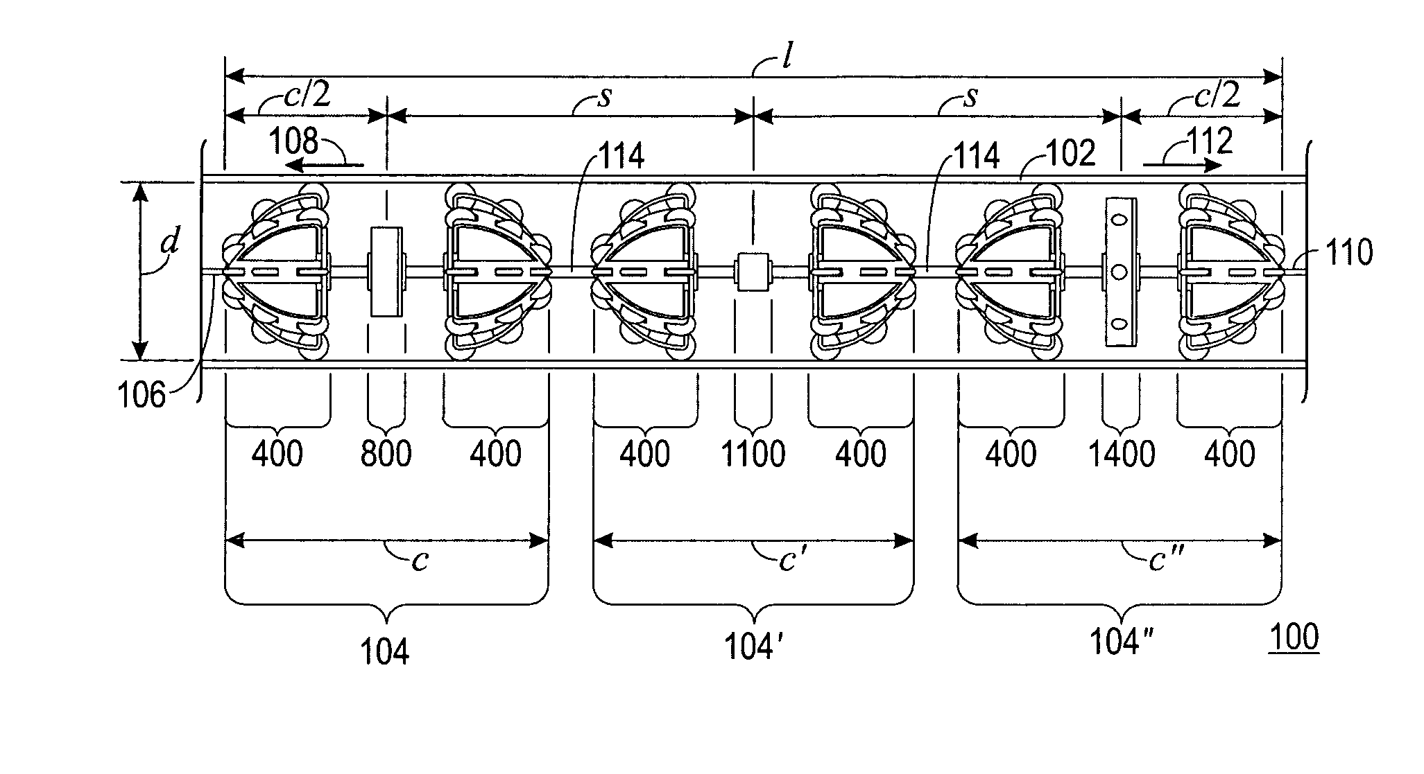
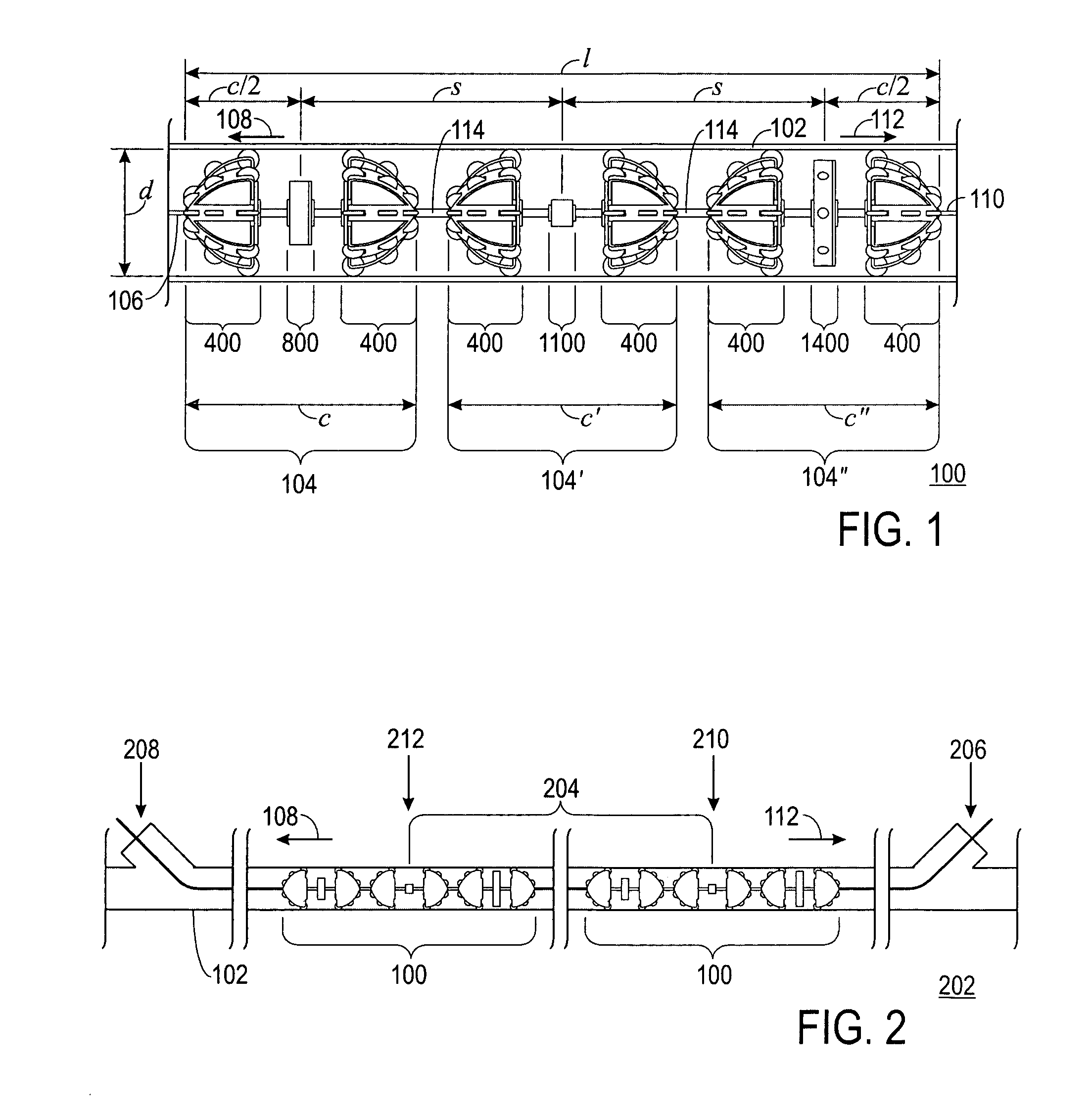
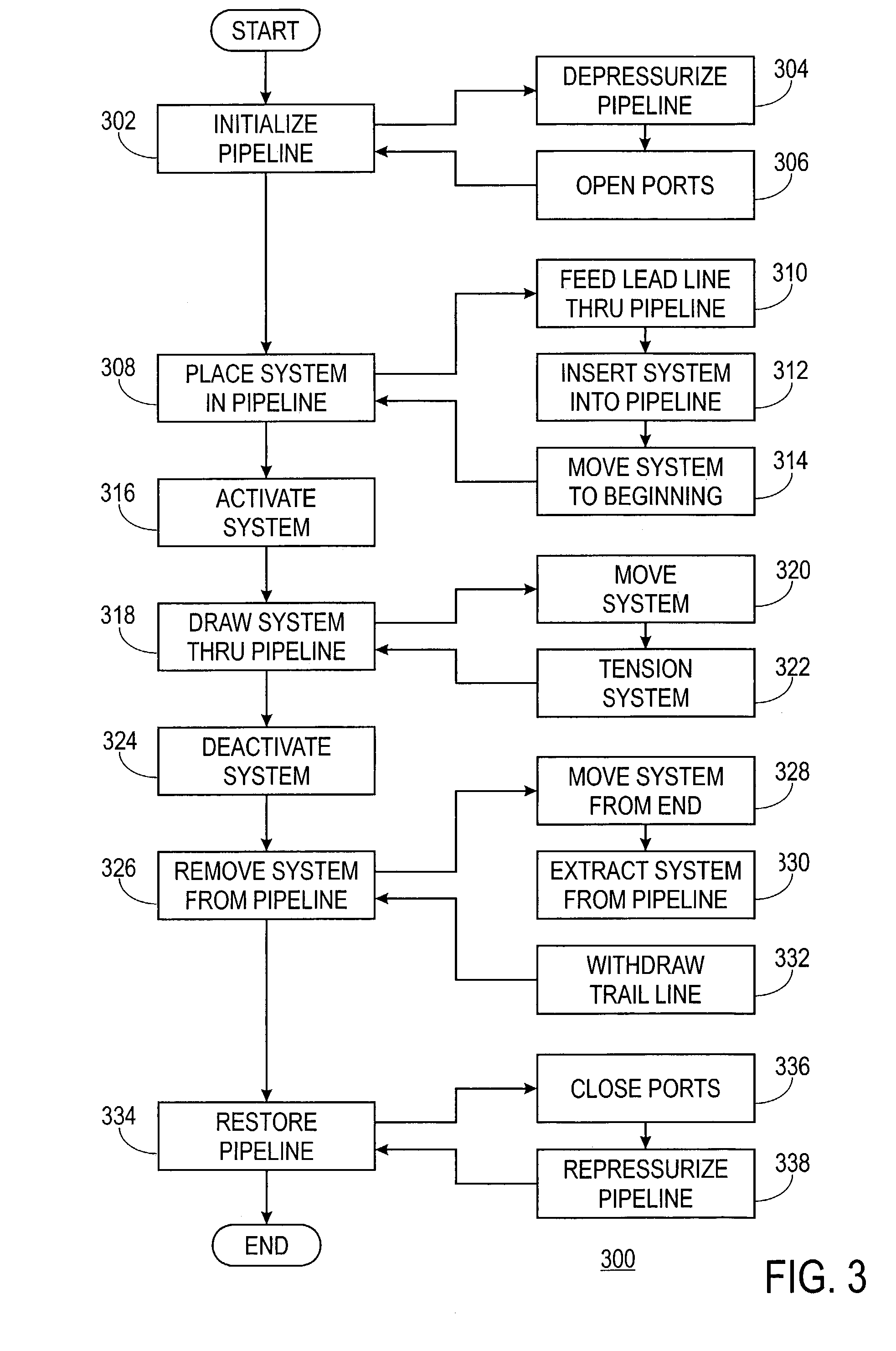
[0052]FIG. 1 shows a side view of a pipe-inspection system 100 in use within a pipeline 102, FIG. 2 shows a side view of a portion 202 of pipeline 102 in which pipe-inspection system 100 is in use, and FIG. 3 shows a block diagram depicting a process 300 for operation of pipe-inspection system 100 in accordance with a preferred embodiment of the present invention. The following discussion refers to FIGS. 1 through 3.

[0053]Pipe-inspection system 100 is made up of a transmission cluster 104 and a reception cluster 104″. System 100 may also contain one or more intermediate clusters 104′ bet...


PUM


Abstract

A pipe-inspection system (100) is provided. The system (100) is made up of a transmission cluster (104) incorporating a transmission unit (800) between first and second wheeled guidance units (400), and a reception cluster (104″) incorporating a reception unit (1400) between third and fourth wheeled guidance units (400). Each wheeled guidance unit (400) contains a plurality of wheels (416) radially disposed in each of a plurality of planes (420, 426, 432). Transmission unit (800) contains a transmission device (1004). Reception unit (1400) contains a reception device (1604). The system (100) is compatible with RFEC inspection techniques to inspect a pipeline (102), where transmission and reception devices (1004, 1604) are an RFEC transmitter and receiver, respectively. A lead line (106) is attached to the first guidance unit (400) to move the system (100) in a forward direction (108). Similarly, a trail line (110) is attached to the fourth guidance unit (400″) to move the system (100) in a reverse direction (112).

Description

TECHNICAL FIELD OF THE INVENTION[0001]The present invention relates to the field of pipe inspection. More specifically, the present invention relates to the field of pipe inspection by electronic means.BACKGROUND OF THE INVENTION[0002]Pipelines develop flaws over time. If left uncorrected, such flaws may eventually result in catastrophic failure of the pipeline. Such a catastrophic failure may result in lost services and revenues. Because a pipeline may fail without warning, early detection of flaws is fundamental to preventing catastrophic failure.[0003]One method of inspection that has proven successful for pipelines in the field is the eddy-current technique. In the eddy-current technique, an electromagnetic field is induced within the pipeline. Flaws in the pipeline distort a component of this field. Analysis of these distortions locates and defines flaws in the pipeline.[0004]In order to perform an in-field inspection, an electronic inspection system is passed through the pipel...

Claims


Application Information

Patent Timeline
Patent Type & Authority Patents(United States)
IPC IPC(8): F16L55/26F16LF17D5/00G01M99/00
CPCF17D5/00
Inventor STOUT, JOHN HUGORICHMOND, KELLY THOMAS
Owner ARIZONA PUBLIC SERVICE
Why Eureka
Try Eureka