Measuring apparatus

a technology of measuring apparatus and measuring rod, which is applied in the direction of instruments, heat measurement, thermometer details, etc., can solve the problems of measuring error and remaining measurement error

Inactive Publication Date: 2006-12-05
FUJIFILM HLDG CORP +1
View PDF13 Cites 18 Cited by
  • Summary
  • Abstract
  • Description
  • Claims
  • Application Information

AI Technical Summary

Benefits of technology

[0021]In view of the foregoing observations and description, the primary object of the present invention is to provide a measuring apparatus in which deterioration of measuring accuracy due to thermal expansion of the sensor unit is suppressed and the measuring accuracy is high.
[0047]In accordance with the present invention, a constant temperature system such as an incubator the temperature of which is highly controllable is provided, the measuring means is spatially isolated from the surroundings by placing it in the measuring system, the temperature of the measuring system is measured by the temperature measuring means and temperature change of the sensor unit after it is conveyed to the measuring system from the constant temperature system is estimated by the controlling means on the basis of the temperature difference between the temperature of the constant temperature system (the predetermined temperature) and the measured temperature of the measuring system, and the conveyor means and the measuring means is driven by the controlling means to convey the sensor unit to the measuring system to perform the measurement within a time for which the temperature of the sensor unit does not change from the predetermined temperature by a temperature range which is larger than an acceptable temperature range or in a time range for which the temperature of the sensor unit is kept in a particular temperature range, whereby fluctuation in temperature of the sensor unit upon measurement is suppressed and deterioration in measuring accuracy is prevented. With this arrangement, the temperature of the sensor unit upon measurement can be accurately controlled irrespective of relatively rough temperature control in the measuring system.
[0052]In the first measuring apparatus of the present invention, since a constant temperature system such as an incubator the temperature of which is highly controllable is provided, the measuring means is spatially isolated from the surroundings by placing it in the measuring system, the temperature of the measuring system is measured by the temperature measuring means and temperature change of the sensor unit after it is conveyed to the measuring system from the constant temperature system is estimated by the controlling means on the basis of the temperature difference between the temperature of the constant temperature system (the predetermined temperature) and the measured temperature of the measuring system, and the conveyor means and the measuring means is driven by the controlling means to convey the sensor unit to the measuring system to perform the measurement within a time for which the temperature of the sensor unit does not change from the predetermined temperature by a temperature range which is larger than an acceptable temperature range, fluctuation in temperature of the sensor unit upon measurement can be suppressed and accordingly deterioration in measuring accuracy can be prevented.
[0053]In the second measuring apparatus of the present invention, since a constant temperature system such as an incubator the temperature of which is highly controllable is provided, the measuring means is spatially isolated from the surroundings by placing it in the measuring system, the temperature of the measuring system is measured by the temperature measuring means and temperature change of the sensor unit after it is conveyed to the measuring system from the constant temperature system is estimated by the controlling means on the basis of the temperature difference between the temperature of the constant temperature system (the predetermined temperature) and the measured temperature of the measuring system, and the conveyor means and the measuring means is driven by the controlling means to convey the sensor unit to the measuring system to perform the measurement in a time range for which the temperature of the sensor unit is kept in a particular temperature range, fluctuation in temperature of the sensor unit upon measurement can be suppressed and accordingly deterioration in measuring accuracy is prevented.

Problems solved by technology

Conventionally, there has been a problem that the position of the interface changes each time the same sensor unit is mounted on the measuring portion, which can result in a measuring error.
However, these inventor's investigation has revealed that even if the position of the sensor unit is adjusted in this manner, there still remains a measuring error (an error produced when the state of light reflected in total internal reflection is measured) due to displacement of the interface due to thermal expansion of the sensor unit.

Method used


Image

  • Measuring apparatus
  • Measuring apparatus
  • Measuring apparatus

Examples


Embodiment Construction

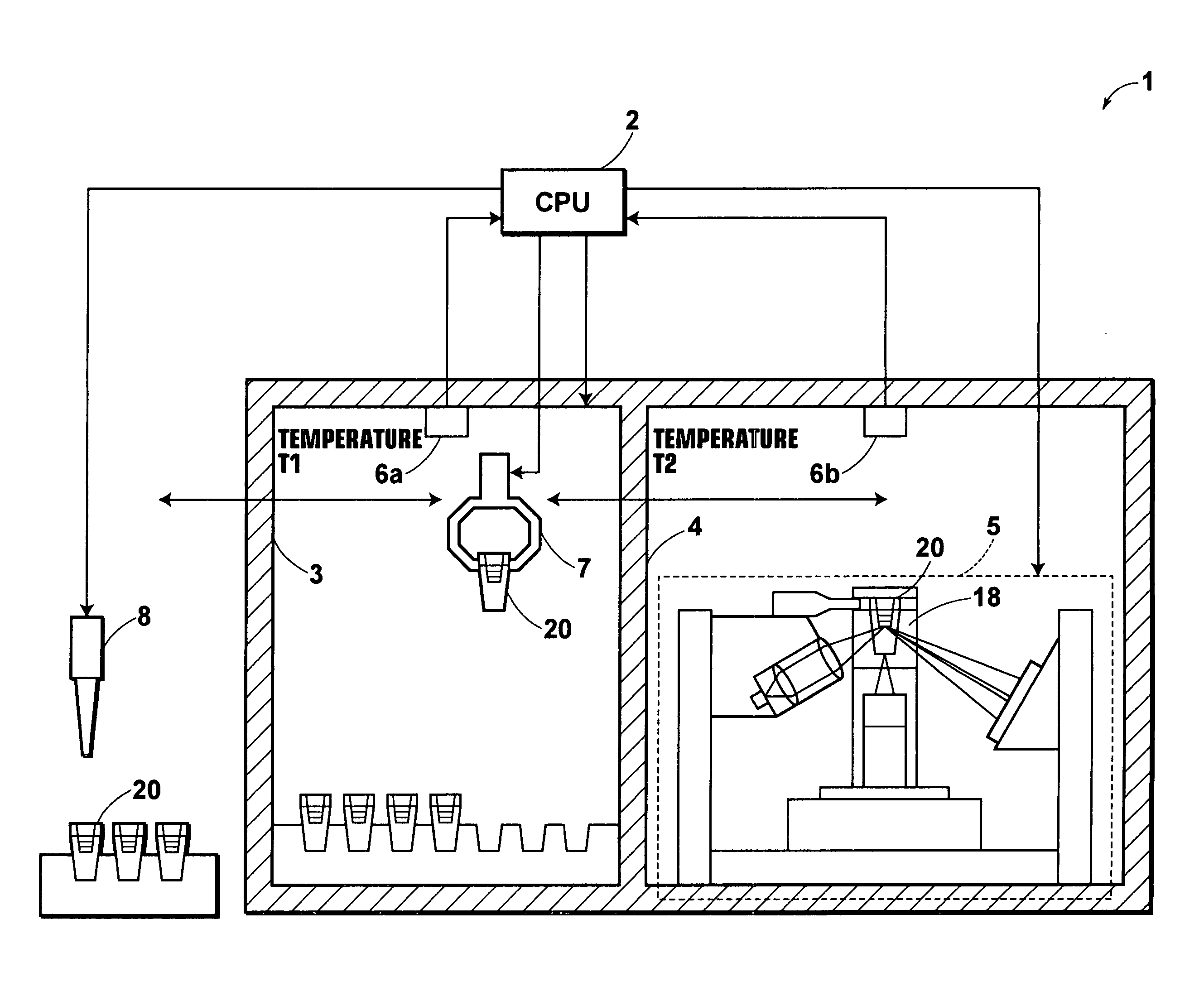
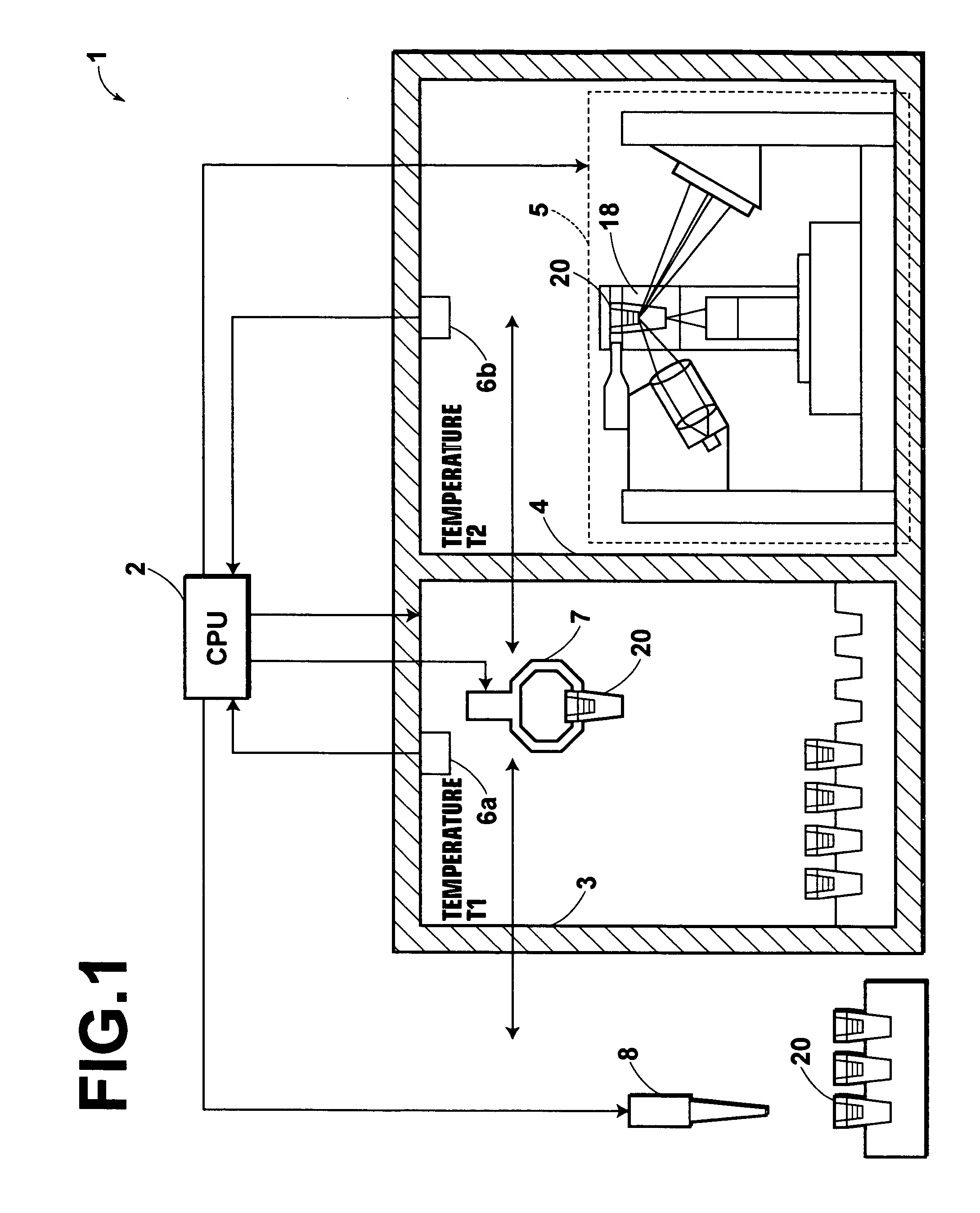
[0067]In FIG. 1, a measuring apparatus 1 in accordance with a first embodiment of the present invention comprises a sensor unit 20 to which a sample is dispensed, a surface plasmon resonance sensor 5 which analyzes the sample dispensed to the sensor unit 20, a measuring system 4 which accommodates the measuring means (the surface plasmon resonance sensor) 5, a constant temperature system 3 which is controlled to be at a predetermined temperature and stores the sensor unit 20, a temperature sensor 6a which measures the temperature of the measuring system, a temperature sensor 6b which measures the temperature of the measuring system 4, a conveyor means 7 which selectively positions the sensor unit 20 in a predetermined position in the measuring system 4 or in the constant temperature system 3, a dispenser 8 which dispenses the sample to the sensor unit 20, and a CPU (controlling means) 2 which controls the surface plasmon resonance sensor 5, the conveyor means 7 and the dispenser 8.

[...


PUM

PropertyMeasurementUnit
temperatureaaaaaaaaaa
diameteraaaaaaaaaa
diameteraaaaaaaaaa

Abstract

In a surface plasmon resonance sensor, a sensor unit includes a dielectric block, a thin film layer which is formed on the upper surface of the dielectric block, and a sample holding portion. An incubator is provided, the surface plasmon resonance sensor is spatially isolated from the surroundings by placing it in the measuring system, the temperature of the measuring system is measured and temperature change of the sensor unit after it is conveyed to the measuring system from the incubator is estimated on the basis of the temperature difference between the temperature of the incubator and the temperature of the measuring system, and the sensor unit is conveyed to the measuring system to perform the measurement within a time for which the temperature of the sensor unit does not unacceptably change.

Description

BACKGROUND OF THE INVENTION[0001]1. Field of the Invention[0002]This invention relates to a measuring apparatus such as a surface plasmon resonance sensor for analyzing a material in a sample on the basis of generation of surface plasmon.[0003]2. Description of the Related Art[0004]In metal, free electrons vibrate in a group to generate compression waves called plasma waves. The compression waves generated in a metal surface are quantized as surface plasmon.[0005]There have been proposed various surface plasmon resonance sensors for quantitatively analyzing a material in a sample utilizing a phenomenon that such surface plasmon is excited by light waves. Among those, one employing a system called “Kretschmann configuration” is best known. See, for instance, Japanese Unexamined Patent Publication No. 6(1994)-167443.[0006]The surface plasmon resonance sensor using the Kretschmann configuration basically comprises a dielectric block shaped, for instance, like a prism, a metal film whic...

Claims


Application Information

Patent Timeline
Patent Type & Authority Patents(United States)
IPC IPC(8): G01K13/00G01N21/55G01N21/01G01N21/41G01N21/27
CPCG01N21/553
Inventor SATO, SHU
Owner FUJIFILM HLDG CORP
Why Eureka
Try Eureka