Particle counting method and particle counter

a particle counting and particle technology, applied in the field of particle counting methods and particle counters, can solve the problems of increasing the size of light source units, further restricting the use of transmission type lenses in optical systems, and the inability to control the particles in semiconductor integrated circuit manufacturing systems to keep and improve manufacturing yield, so as to improve the accuracy of detecting charged particles, the effect of effectively measuring particles

Inactive Publication Date: 2006-12-05
PANASONIC CORP
View PDF11 Cites 9 Cited by
  • Summary
  • Abstract
  • Description
  • Claims
  • Application Information

AI Technical Summary

Benefits of technology

[0011]These means can constitute a particle counter capable of quickly and easily measuring and evaluating the particles having particle sizes, in particular, not larger than 50 nm to obtain the particle size distribution of particles in a process aerosol in a reduced pressure vapor phase apparatus.
[0030]These means can constitute a particle counter that can quickly and easily in-situ measure the particles having particle sizes, in particular, not larger than 50 nm and calculate the particle size distribution.

Problems solved by technology

In order to produce the ultraviolet light having a smaller wavelength, an excimer laser needs to be used, which in turn increases the size of a light source unit and further limits the use of a transmission type lens in an optical system.
Therefore, it is impossible to control the particles in the semiconductor integrated circuit manufacturing system to keep and improve a manufacturing yield by using the Rayleigh scattering method described above.

Method used


Image

  • Particle counting method and particle counter
  • Particle counting method and particle counter
  • Particle counting method and particle counter

Examples


first embodiment

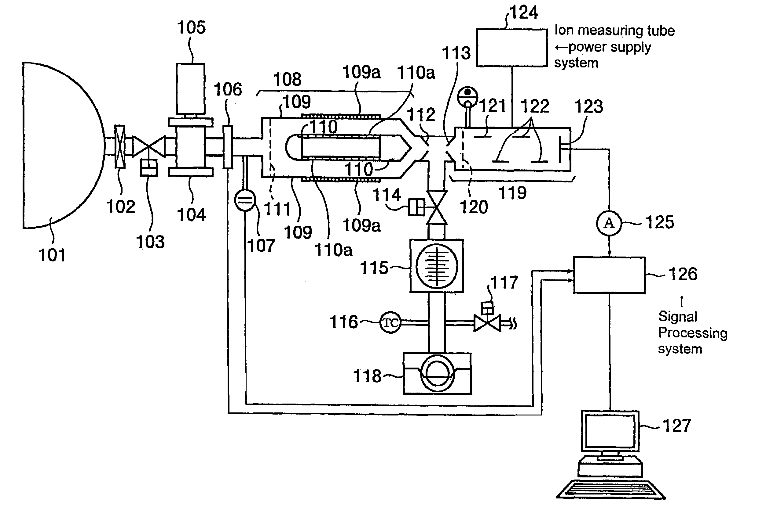
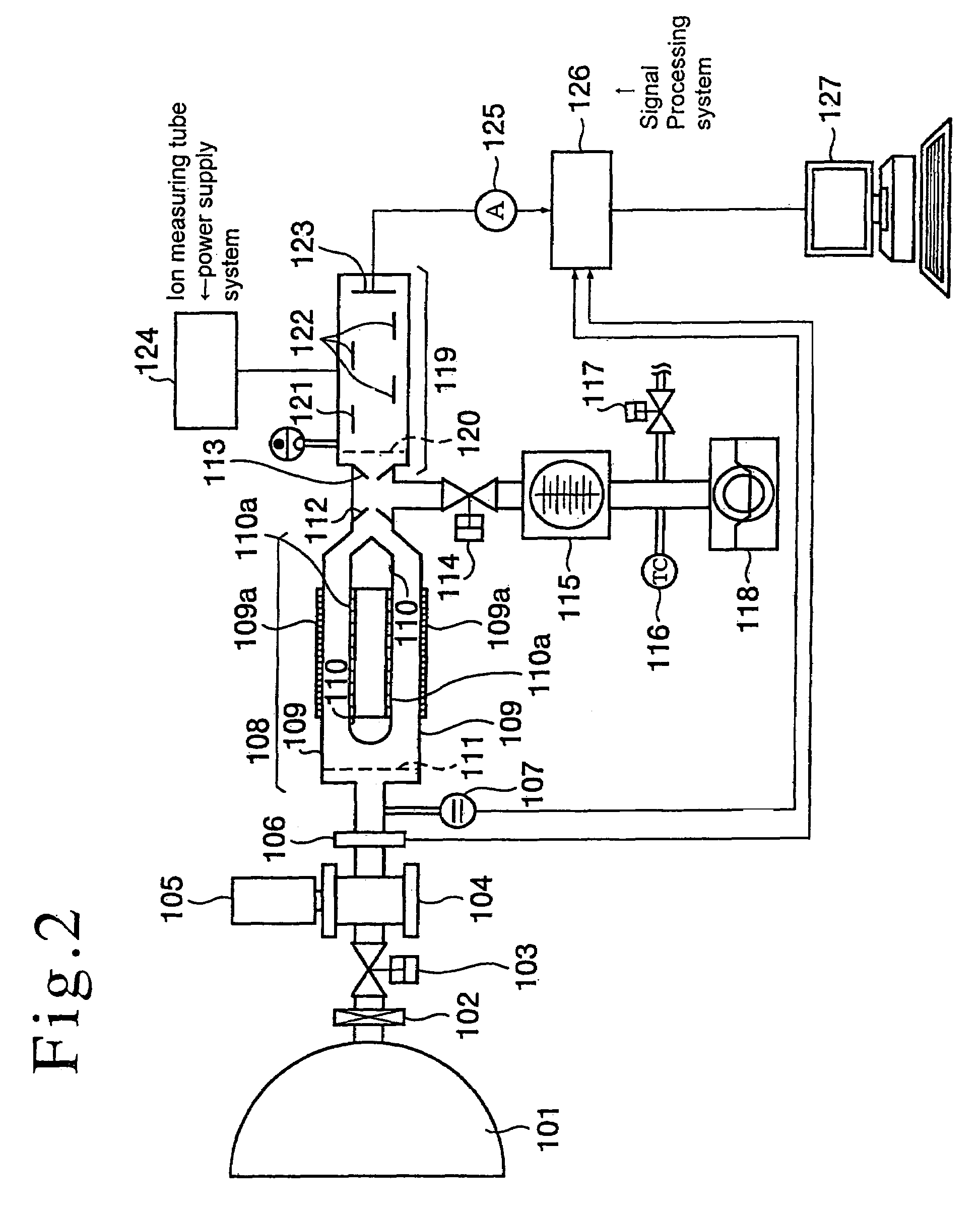
[0043]Next, the preferred embodiment in accordance with the present invention will be described in detail. FIG. 2 is a block diagram to schematically show the general configuration of a particle counter in accordance with the present embodiment. In FIG. 2, a reference numeral 101 denotes a reduced pressure process apparatus process chamber; a reference numeral 102 denotes an aerosol intake valve that is connected to the reduced pressure process apparatus process chamber 101 and takes in aerosol from the reduced pressure apparatus process chamber 101; a reference numeral 103 denotes a intake conductance adjusting valve that adjusts the intake of the aerosol in the aerosol intake valve 102; a reference numeral 104 denotes a charging device that charges the aerosol introduced and a group of particles existing therein; a reference numeral 105 denotes an Ar2 excimer light source that conducts vacuum ultraviolet ray irradiation in a charging process by the charging device 104 described ab...

second embodiment

[0067]Next, the second embodiment in accordance with the present invention will be described in detail. FIG. 4 is a block diagram to show the general configuration of a particle counter in accordance with the present embodiment. The particle counter of the present embodiment is connected in a vapor phase to a process chamber 301, in particular, in a chemical vapor deposition (CVD) or a physical vapor deposition (PVD) that is conducted in a reduced pressure vapor phase or a dry etching in a semiconductor integrated circuit manufacturing process system in conformity with an ultra-fine design rule (130 nm or less). In the present embodiment, the process chamber 301 is a process apparatus conducting a physical or chemical reaction in the vapor phase, and has a function as an aerosol supply source.

[0068]This particle counter is provided with an aerosol intake valve 302 connected to the process chamber 301, a charging device 303 for charging the aerosol introduced from the aerosol intake ...


PUM

PropertyMeasurementUnit
particle sizeaaaaaaaaaa

Abstract

A particle counter counts particles in aerosol having a particle size of from 2 nm to 50 nm in an operating pressure range from an atmospheric pressure through a reduced pressure to a low vacuum and calculate a particle size distribution. The particle counter charges particles in the aerosol and applies an electrostatic field thereto, and mixes the aerosol with a non-charged sheath gas flow shaped like a laminar flow whereby the respective particles separate into traces depending on their particle size where they can be counted. Further, by using an electron multiplier for exciting cluster ions to detect the charged particles and operating it as a high-pass filter, even if the number density of the particles is small, it is possible to effectively count the particles.

Description

RELATED APPLICATIONS[0001]This is a division of parent application Ser. No. 10 / 200,499, filed Jul. 23, 2002 now abandoned.BACKGROUND OF THE INVENTION[0002]1. Field of the Invention[0003]The present invention relates to measuring and evaluating the particle size distribution of particles in aerosol and, in particular, can quickly and easily measure and evaluate particles having a particle size not more than 100 nm and thus is suitable for in-situ measuring particles in a reduced pressure vapor phase process apparatus and a clean room used for manufacturing a semiconductor integrated device and a liquid crystal display device and contributes to the improvement of the manufacturing yield of these devices.[0004]2. Description of the Related Art[0005]As an example in the related art, a particle size measuring unit using a laser scattering method, which is a mainstream at present. This is a method of measuring the particle sizes of particles in aerosol and utilizes the phenomenon that whe...

Claims


Application Information

Patent Timeline
Patent Type & Authority Patents(United States)
IPC IPC(8): G01N27/00G01N27/62G01N15/06
CPCG01N15/0656
Inventor YOSHIDA, TAKEHITOSUZUKI, NOBUYASUMAKINO, TOSHIHARUYAMADA, YUKA
Owner PANASONIC CORP
Why Eureka
Try Eureka