
Injection locked high frequency oscillator

a high frequency oscillator and locking technology, applied in the field of harmonic high frequency oscillators, can solve the problem of increasing spurious for a second harmonic component, and achieve the effects of reducing phase noise, increasing frequency stability, and expanding the pull-in rang

Inactive Publication Date: 2006-12-05
NIHON DEMPA KOGYO CO LTD +1
View PDF3 Cites 2 Cited by
  • Summary
  • Abstract
  • Description
  • Claims
  • Application Information

AI Technical Summary

Benefits of technology

[0017]It is an object of the present invention to provide an injection locked multiple harmonic high frequency oscillator which is capable of suppressing spurious to increase the frequency stability, and reducing phase noise to expand a pull-in range.

Problems solved by technology

This causes a problem of increased spurious for a second harmonic component.

Method used


Image

  • Injection locked high frequency oscillator
  • Injection locked high frequency oscillator
  • Injection locked high frequency oscillator

Examples


Embodiment Construction

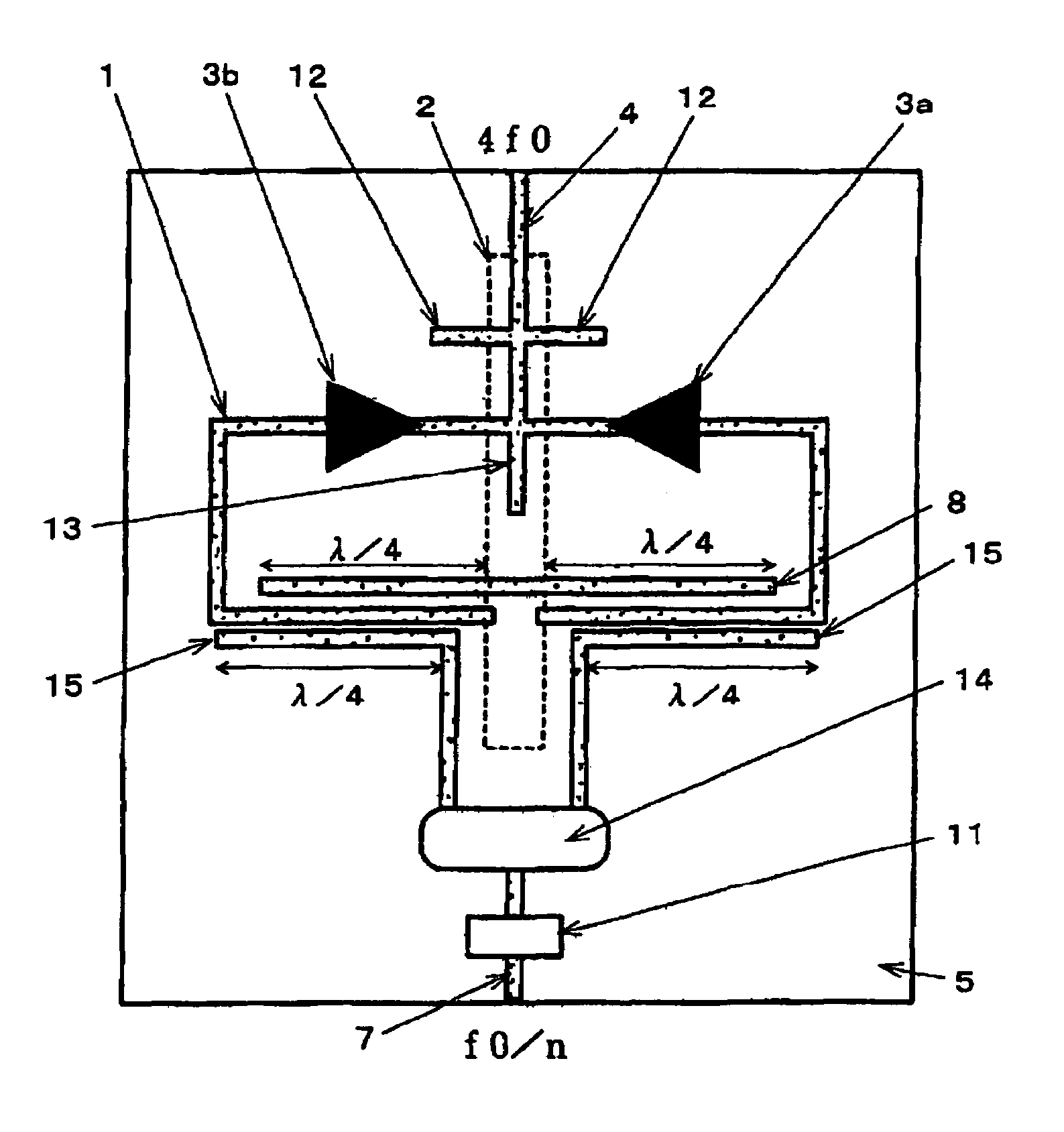
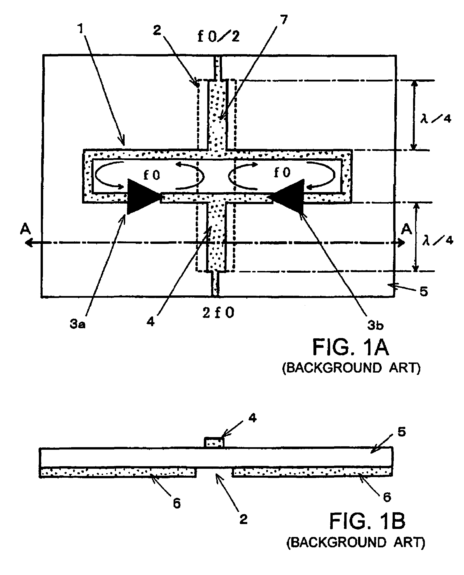
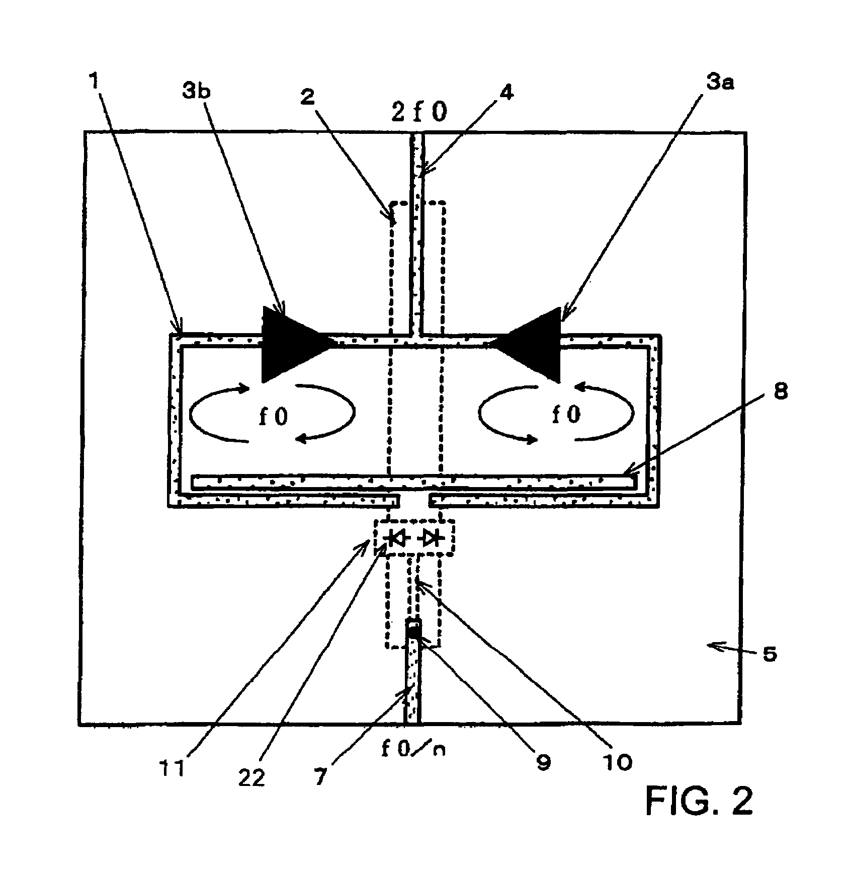
[0029]A second-harmonic high frequency oscillator according to a preferred embodiment of the present invention illustrated in FIG. 2 adds a mechanism for injecting a synchronization signal to the oscillator illustrated in FIGS. 1A and 1B. In FIG. 2, components identical to those in FIGS. 1A and 1B are designated the same reference numerals, and repeated description thereon is simplified.

[0030]The second-harmonic oscillator illustrated in FIG. 2, like the one illustrated in FIGS. 1A and 1B, comprises dielectric substrate 5; a pair of amplifiers 3a, 3b for oscillation mounted on one principal surface of dielectric substrate 5; microstrip line 1 used as a high frequency transmission line to which output line 4 is connected; and slot line 2 which functions as an electromagnetic coupling member for providing opposite phase oscillation. Slot line 2 is formed by creating an aperture line in ground conductor 6 disposed over the entirety of the other principal surface of dielectric substrate...


PUM


Abstract

A push-push high frequency oscillator comprises a pair of amplifiers for oscillation, a loop-shaped microstrip line for connecting inputs of the pair of amplifiers to each other and connecting outputs of the pair of amplifiers to each other, a slot line disposed between the inputs and the outputs of the pair of amplifiers for electromagnetically coupling with the microstrip line, a nonlinear circuit for enhancing the level of harmonic components in an applied synchronization signal, a coupler circuit for electromagnetically coupling the output of the nonlinear circuit to the microstrip line, and a filter circuit disposed at the output of the nonlinear circuit. The filter circuit filters harmonic components of the synchronization signal such that the two oscillation systems are injected with the same frequency components as the fundamental wave or frequency components twice as high as the fundamental wave to increase frequency stability.

Description

BACKGROUND OF THE INVENTION[0001]1. Field of the Invention[0002]The present invention relates to a harmonic high frequency oscillator for generating frequency outputs, which are even-order harmonics of a fundamental wave of an oscillation frequency through so-called push-push oscillation for use in a millimeter-wave band and a microwave band, and more particularly, to a high frequency oscillator which achieves improved phase noise characteristics and frequency pull-in through injection locking.[0003]2. Description of the Related Art[0004]A push-push oscillation based oscillator is known as suitable for generating oscillation signals in a millimeter-wave band and a microwave band. The oscillator based on push-push oscillation based employs a pair of oscillation circuits which operate at the same fundamental frequency but in opposite phases to each other, and combines the outputs from these oscillation circuits to cancel out the fundamental wave component and extract even-order harmon...

Claims


Application Information

Patent Timeline
Patent Type & Authority Patents(United States)
IPC IPC(8): H03B7/12H03B5/18H03L7/24H03B19/18
CPCH03B5/1852
Inventor AIKAWA, MASAYOSHITANAKA, TAKAYUKIASAMURA, FUMIOOITA, TAKEO
Owner NIHON DEMPA KOGYO CO LTD
Learn More