Lens assembly for an image sensor

a technology for image sensors and lens assemblies, which is applied in the field of lens assemblies for image sensors, can solve the problems of excessive power of the first lens, excessive increase in the sensitivity of the whole image lens assembly, and consequently affect the function and effect of the lens assembly, so as to reduce improve the ability of restraining power, and improve the sensitivity of decentration and the aberration correction effect of the whole lens assembly in accordance with the present invention

Active Publication Date: 2006-12-05
LARGAN PRECISION
View PDF2 Cites 149 Cited by
  • Summary
  • Abstract
  • Description
  • Claims
  • Application Information

AI Technical Summary

Benefits of technology

[0008]The primary objective of the present invention is to provide a lens assembly for an image sensor capable of reducing the sensitivity of decentration comprises an aperture, a first lens, a second lens and a third lens which are arranged sequentially from the object side. The first lens is a planoconvex lens or a positive meniscus lens whose convex surface faces the object side; the second lens is a negative meniscus lens with a convex surface facing the image side and, at least, has an aspherical surface; and the third lens is a positive meniscus lens with a convex surface facing the object side and, at least, has an aspherical surface. Each lens of this arrangement has an improved capability of restraining the power, so that the sensitivity of decentration and the aberration-correction effect of the whole lens assembly in accordance with the present invention can be effectively improved.

Problems solved by technology

However, this lens assembly has some disadvantages.
For example, the power of the first lens is excessively strong.
However, if all the respective lenses are strong in power, the sensitivity of decentration of the whole image lens assembly will be excessively increased, so that the function and effect of the lens assembly is consequently affected in a detrimental way.

Method used


Image

  • Lens assembly for an image sensor
  • Lens assembly for an image sensor
  • Lens assembly for an image sensor

Examples


Embodiment Construction

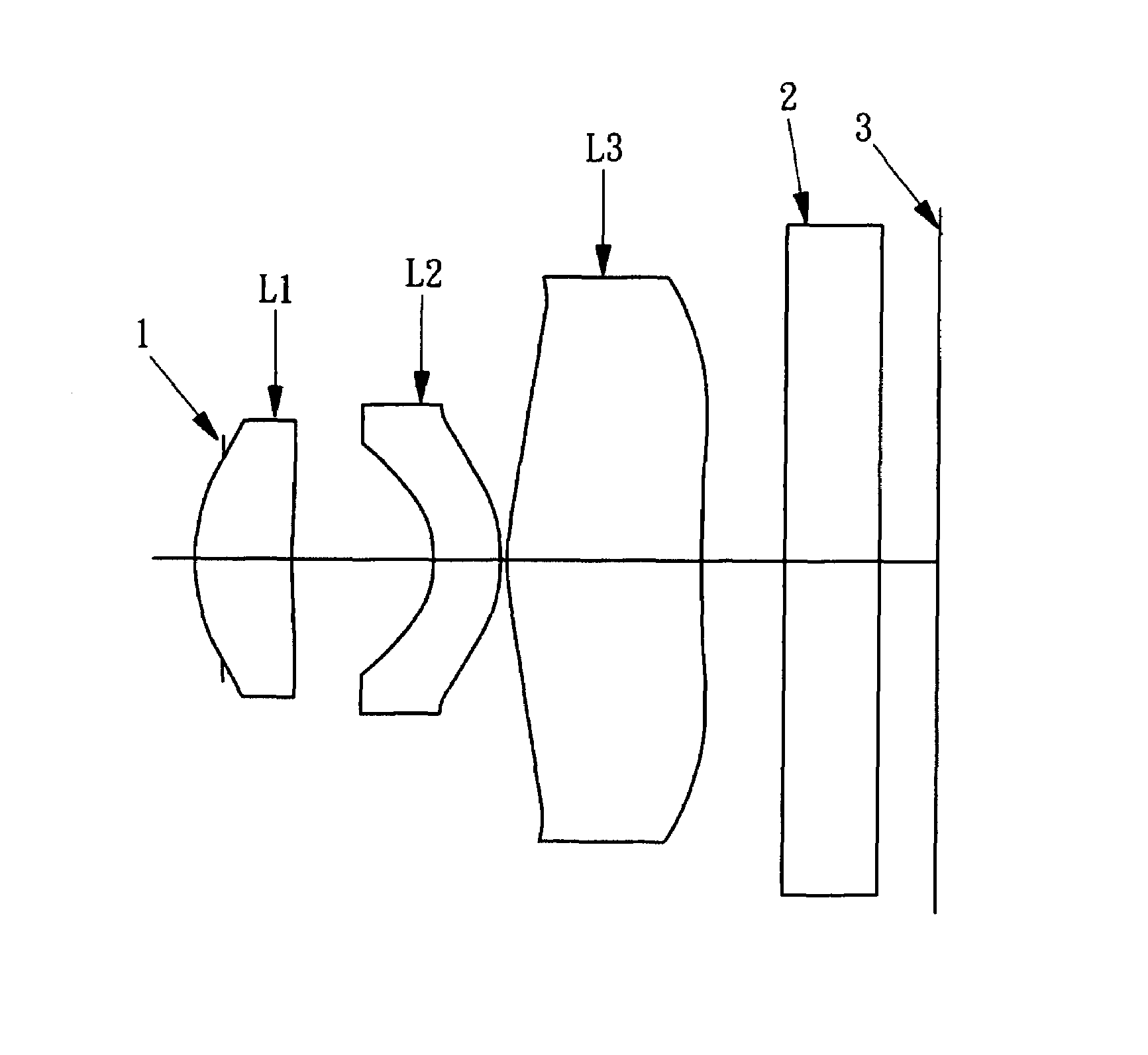
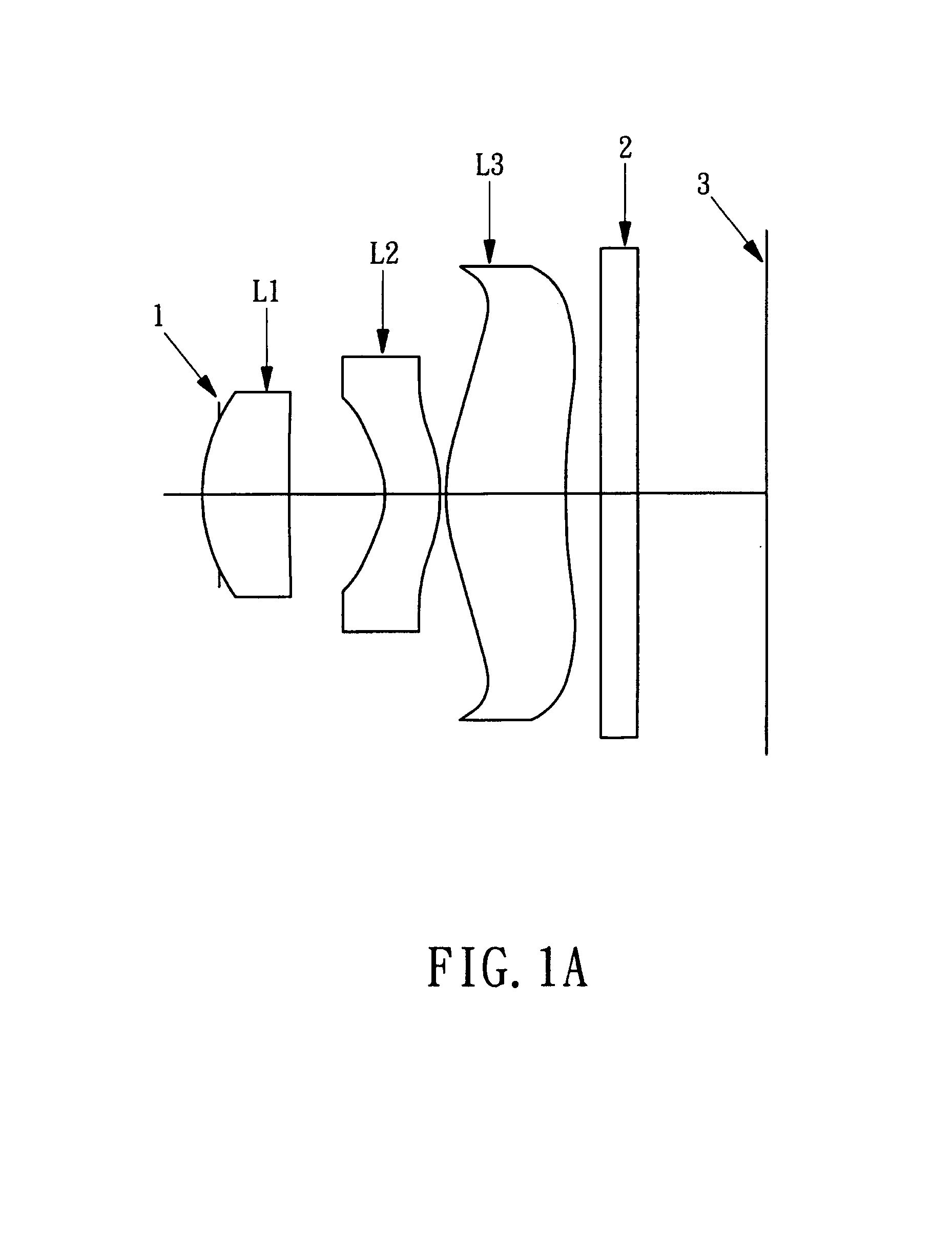
[0040]With reference to the respective figures, a lens assembly for an image sensor comprises an aperture 1, a first lens L1, a second lens L2, a third lens L3, a parallel flat glass 2 and an image plane 3 (the aperture 1 and the image plane 3 are indicated by the lines), which are arranged sequentially from the object side.

[0041]The aperture 1 is disposed nearest to the object side.

[0042]The first lens L1 can be a planoconvex lens or a positive meniscus lens whose convex surface faces the object side. The first lens L1 as shown in FIGS. 7–12 is a planoconvex lens L1, and the first lens L1 shown in the rest figures is a meniscus lens. The first lens L1 according to the present invention is more capable of restraining the increased power than the conventional invention.

[0043]The second lens L2 is a negative meniscus lens with a convex surface facing the image side and at least has an aspherical surface. The second lens L2 as shown in FIGS. 1–12 has two aspherical surfaces.

[0044]The t...


PUM


Abstract

A lens assembly for an image sensor comprises an aperture, a first lens, a second lens and a third lens, which are arranged sequentially from the object side. The first lens is a planoconvex lens or a positive meniscus lens whose convex surface faces the object side; the second lens is a negative meniscus lens with a convex surface facing the image side and at least has an aspherical surface; and the third lens is a positive meniscus lens with a convex surface facing the object side and, at least, has an aspherical surface. The sensitivity of decentration and the aberration-correction effect of the whole lens assembly in accordance with the present invention can be effectively improved.

Description

BACKGROUND OF THE INVENTION[0001]1. Field of the Invention[0002]The present invention relates to a lens assembly for an image sensor, which is comprised of an aperture, a first lens, a second lens and a third lens, each lens of this assembly has an improved capability of restraining the power, so that the sensitivity of decentration and the aberration-correcting effect of the whole lens assembly in accordance with the present invention can be effectively improved.[0003]2. Description of the Prior Arts[0004]Image sensor has been widely used in different areas nowadays. For example, the mobile phone also has been equipped with such an image sensor comprised of a solid state imaging device and lens, such as Charge Coupled Device (CCD) sensor or Complementary Metal Oxide Semiconductor (CMOS) sensor. With the development of science and technology, the mobile phone is becoming more and more smaller, thereby, the lens in the mobile phone also needs to be miniaturized.[0005]For example, JP ...

Claims


Application Information

Patent Timeline
Patent Type & Authority Patents(United States)
IPC IPC(8): G02B9/14G02B3/02
CPCG02B9/16G02B13/0035
Inventor NODA, SAYURI
Owner LARGAN PRECISION
Why Eureka
Try Eureka