Driving mechanism for a camera lens

a technology of driving mechanism and camera lens, which is applied in the direction of mountings, optics, instruments, etc., can solve the problems of inconvenient use, inconvenient use, and inability to apply in portable products such as mobile phones, and achieve the effect of good control ability

Inactive Publication Date: 2006-12-05
ARIMA COMP
View PDF8 Cites 17 Cited by
  • Summary
  • Abstract
  • Description
  • Claims
  • Application Information

AI Technical Summary

Benefits of technology

[0009]It is therefore an objective of the present invention to provide a lens driving mechanism with good control ability.
[0010]It is another objective of the present invention to provide a lens driving mechanism with high position accuracy.
[0011]It is still another objective of the present invention to provide a lens driving mechanism with a small volume.
[0012]It is another objective of the present invention to provide a lens driving mechanism with low cost.
[0014]When the conductor coil conducts electrical current, a force is induced to push the lens cylinder because the directions of the current and the magnetic line of force are vertical, and the magnitude of the current and the magnetic line of force are directly proportional. The translation of the lens cylinder makes the flange closer and closer to the magnetic body, and then the elastic component exerts a reactive force to the lens cylinder because the elastic component is compressed between the flange and the magnetic body. Thus, the positions of the lens cylinder and the lens element within it are determined by controlling the magnitude of the current for counterbalancing the active force and the reactive force. The positioning accuracy of the lens can be enhanced also, simply by precisely tuning the current magnitude.

Problems solved by technology

Although advanced users may obtain a better effect by manual focus, it may be too difficult for amateur users; therefore, the fully automatic camera has been presented to the public.
Generally, the transmission is achieved by a cam and a gear wheel mechanism, making the transmission extensive and hard to apply in portable products, such as mobile phones.
Consequently, the limitations of traditional cameras with respect to miniaturization are obvious.

Method used


Image

  • Driving mechanism for a camera lens
  • Driving mechanism for a camera lens
  • Driving mechanism for a camera lens

Examples


Embodiment Construction

[0021]Reference will now be made in detail to the present preferred embodiments of the invention, examples of which are illustrated in the accompanying drawings. Wherever possible, the same reference numbers are used in the drawings and the description to refer to the same or like parts.

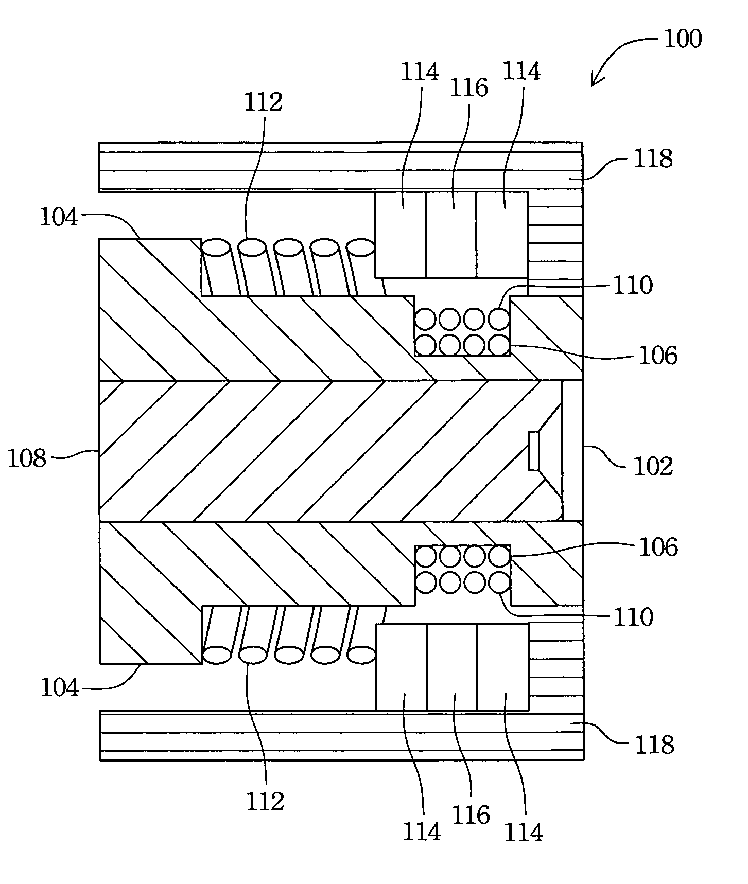
[0022]The basic concept of the present invention is using an active force induced by the interaction of electric current and the magnetic line of force to control the position of a lens. In this way, the lens can be linearly driven forward and backward without any additional part motion but with a high positioning accuracy and by simple control.

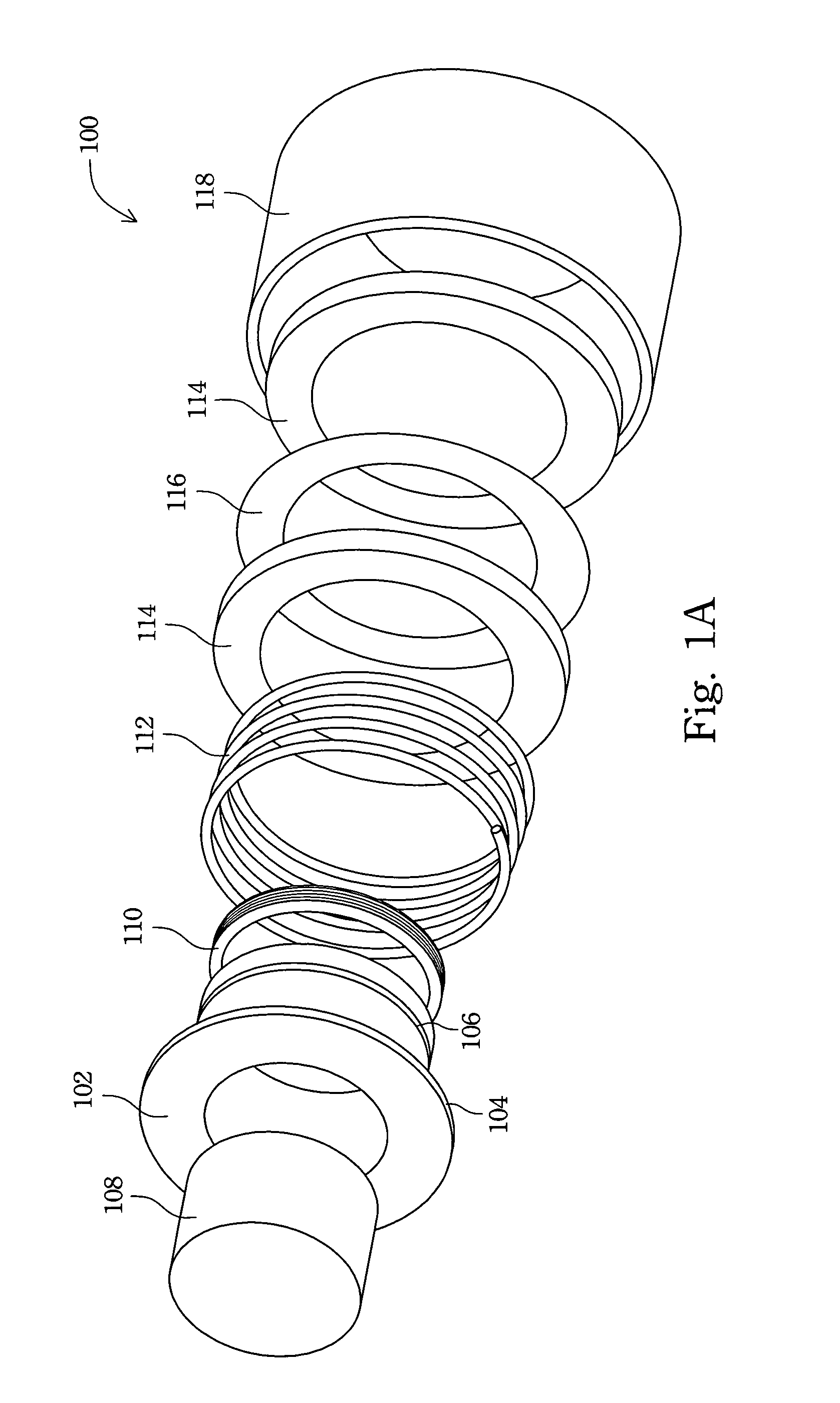
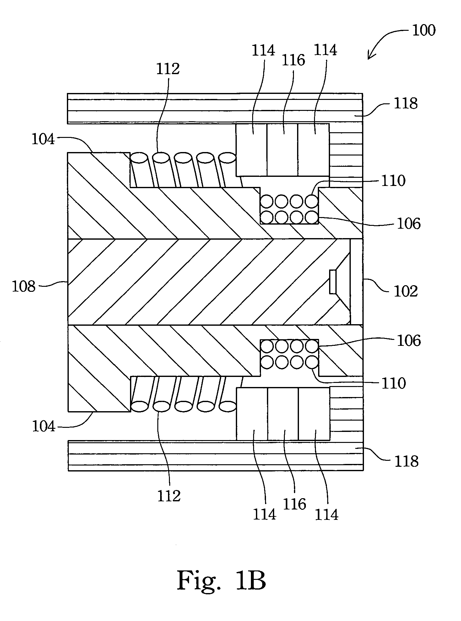
[0023]FIG. 1A illustrates an exploded view of a lens driving mechanism according to an embodiment of the present invention, showing the main elements of a lens driving mechanism 100, including a lens cylinder 102, a lens 108, a conductor coil 110, a coil spring 112, two magnetic bodies 114, an inner yoke 116 between the magnetic bodies 114 and a mechanism cyli...


PUM


Abstract

A camera lens drive mechanism includes a lens cylinder, and the lens hollow is able to fit over a lens. A conductor coil is wound around an outer surface of the lens cylinder, and a coil spring is surrounding the lens hollow cylinder. A magnetic body is opposite to the conductor coil for the magnetic line of force from the magnet can cut across the conductor coil. An active force is induced on the coil when a current is conducted in the conductor coil, and then the lens cylinder is pushed also. The magnitude of the active force can be controlled by adjusting the magnitude of the current in the conductor coil.

Description

BACKGROUND[0001]1. Field of Invention[0002]The present invention relates to a driving mechanism for a camera lens. More particularly, the present invention relates to a driving mechanism for an auto-focus camera lens.[0003]2. Description of Related Art[0004]Due to advances in photography, almost all modern camera equipment has the ability to focus such that an object can be clearly imaged in the camera no matter whether the object is near or far. Adjusting the lens makes the light irradiated into the camera aggregated at an optimum position, the so-called focus, and then an image can be clearly recorded by the camera.[0005]Manual focus is used for tronal cameras; in other words, the position of a traditional camera lens is manually adjusted to a point determined by a user's naked eye. Although advanced users may obtain a better effect by manual focus, it may be too difficult for amateur users; therefore, the fully automatic camera has been presented to the public. A fully automatic ...

Claims


Application Information

Patent Timeline
Patent Type & Authority Patents(United States)
IPC IPC(8): G02B7/02G02B15/14
CPCG02B7/08
Inventor SHU, MAO-ZENHSU, WEN-TSAI
Owner ARIMA COMP
Why Eureka
Try Eureka