Head support device and it's driving method, and drive disk using same

a technology of support device and drive disk, which is applied in the direction of head disposition/mounting, recording information storage, instruments, etc., can solve the problems of trouble, erasure or the like of the already recorded zone, and difficulty in realizing the intended miniaturization, so as to prevent the deterioration of recording characteristics, quick and accurate positioning, and smooth movement

Inactive Publication Date: 2006-12-05
WESTERN DIGITAL TECH INC
View PDF28 Cites 23 Cited by
  • Summary
  • Abstract
  • Description
  • Claims
  • Application Information

AI Technical Summary

Benefits of technology

[0021]In the above configuration, the loci of movements of respective sliders fitted to respective suspensions fixed on the third link and the fourth link in accordance with the rotation of the first link correspond to the circularly arcuate loci identical with movements of respective rotational centers of the third link and the fourth link at the first link. Accordingly, it is possible to realize a head support mechanism wherein the locus is as much straight line as possible in a state that, of the circles being the loci of movements of the respective rotational centers of the third link and the fourth link at the first link in accordance with the rotation of the first link, the circularly arcuate locus subscribed by the slider on the recording medium can be set so that the distance at each point of the locus from the diametric line of the recording medium is lessened and that the slider can be sufficiently floated at the innermost periphery of the recordable zone of the recording medium.
[0035]In the above configuration, the skew angle of the signal conversion element against the recording track can be made very small, and when the mode is shifted from reproducing to recording or from recording to reproducing, the recording head or reproducing head can be quickly and accurately positioned. Also, the direction of magnetic orientation in the circumferential direction of the initialized recording medium is not deflected from the recording magnetic field, and thereby, it is possible to prevent the deterioration of recording characteristics. Accordingly, the signal conversion element can be smoothly moved toward the target track, and it is possible to realize a disk drive wherein the access time for moving the signal conversion element to the target track is shortened.

Problems solved by technology

Particularly, when the mode is shifted from reproducing to recording, it is required to quickly and accurately correct the positioning, or otherwise there arises a problem such that shifting the mode to recording causes the occurrence of trouble such as erasing or the like on the already recorded zone.
In order to lessen the skew, it is necessary to increase the distance from the rotational center of the head support device 291 to the magnetic head, but it is contradictory to the purpose of miniaturization, making it difficult to realize the intended miniaturization.
Also, if the skew of the recording head is increased, deflection will be generated between the magnetic orientation and the recording magnetic field in the circumferential direction of the initialized magnetic recording medium 296, causing the recording characteristics to be deteriorated.

Method used


Image

  • Head support device and it's driving method, and drive disk using same
  • Head support device and it's driving method, and drive disk using same
  • Head support device and it's driving method, and drive disk using same

Examples


first exemplary embodiment

(First Exemplary Embodiment)

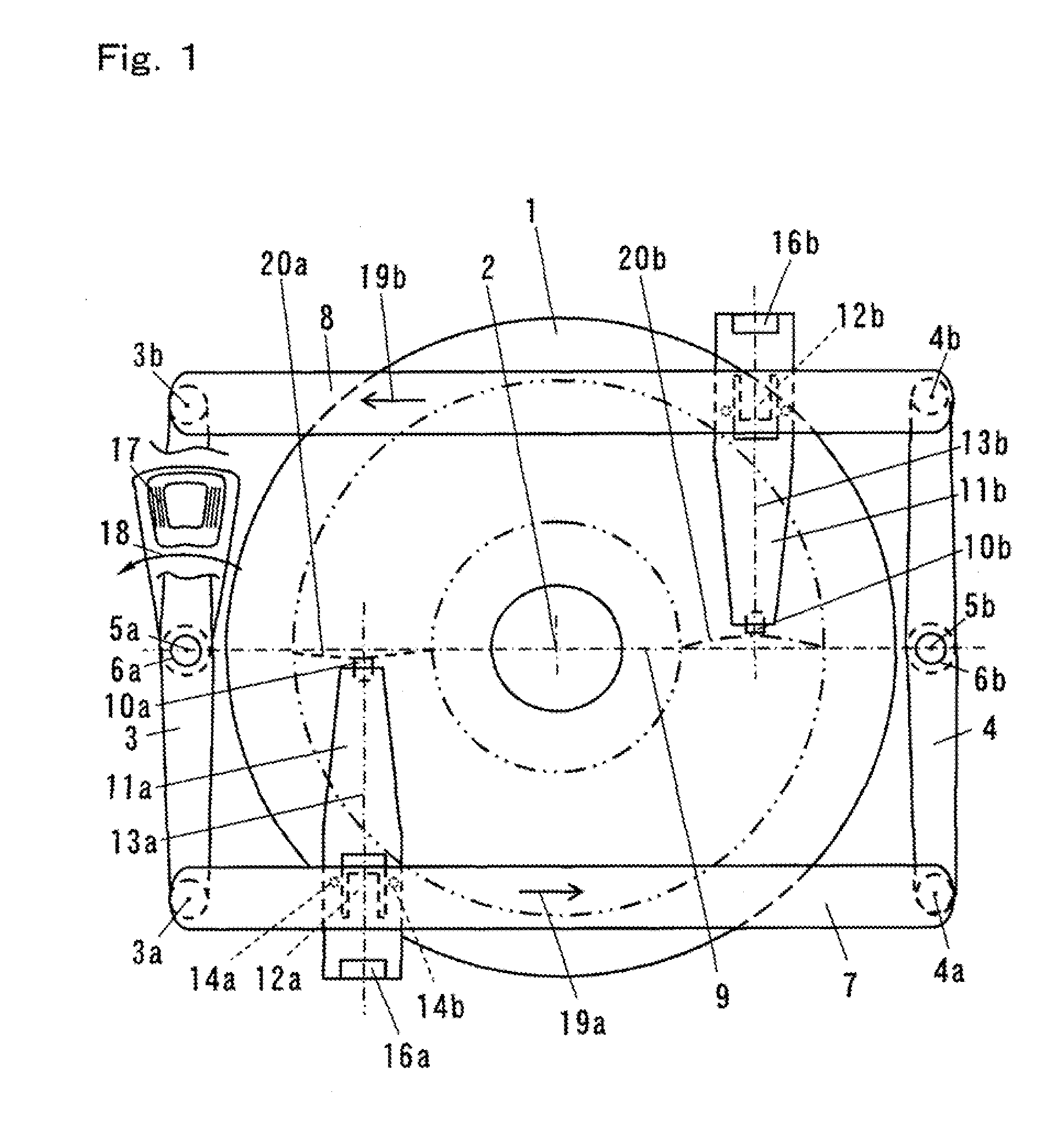
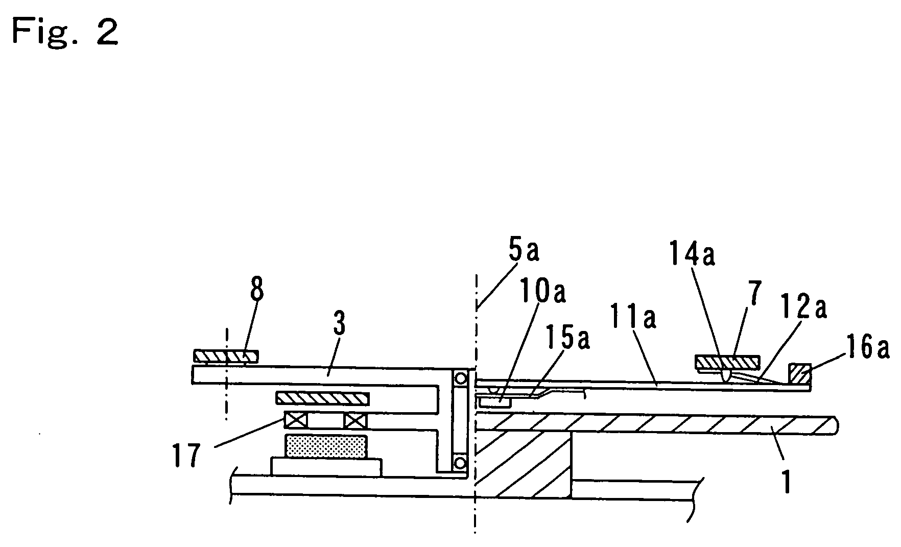
[0068]FIG. 1, FIG. 2 and FIG. 3 illustrates the head support device in the first exemplary embodiment of the present invention. FIG. 1 is a top view of essential components, showing the configuration of the head support device and recording medium in the first exemplary embodiment of the present invention. FIG. 2 is a side view of the essential components. FIG. 3 is a partly enlarged side view of a suspension out of the essential components.

[0069]In FIG. 1 and FIG. 2, recording medium 1 is rotated about rotation center 2 by means of a spindle motor (not shown). There are provided first bearing 6a and second bearing 6b respectively having first rotational center 5a and second rotational center 5b, which respectively rotate first link 3 and second link 4, on the extension of same diametric line 9 with the rotational center 2 of the recording medium 1 therebetween. The distances from the rotation center 2 to the first rotational center 5a and to the second r...

second exemplary embodiment

(Second Exemplary Embodiment)

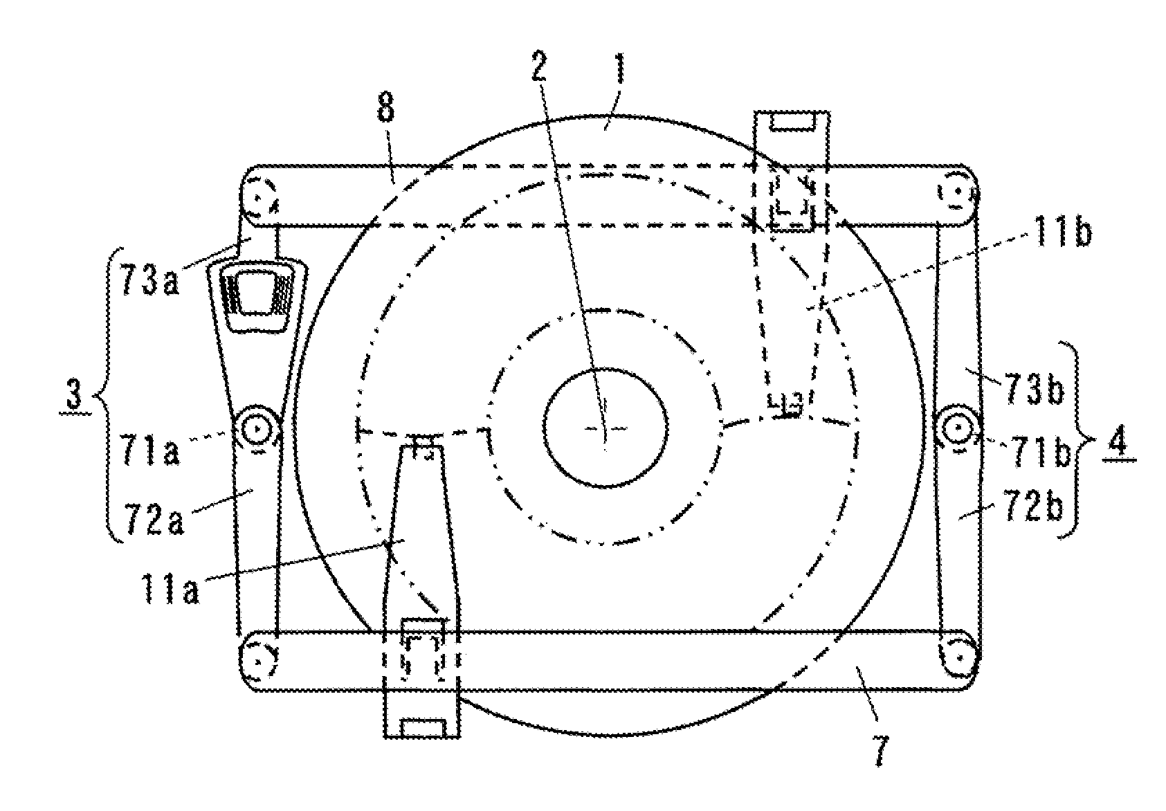
[0155]FIG. 8 and FIG. 9 are diagrams for describing a head support device in the second exemplary embodiment of the present invention. FIG. 8 is a schematic top view showing the positional relations of the third link and the fourth link of the head support device having four suspensions in the second exemplary embodiment, and the fixed suspensions and the recording medium. FIG. 9 is a schematic top view showing another example of positioning of suspensions. In FIG. 8 and FIG. 9, the elements corresponding to the component elements in FIG. 1 of the first exemplary embodiment are given same reference numerals as those in FIG. 1.

[0156]As shown in FIG. 8 and FIG. 9, the first suspension 11a and the third suspension 11c are fixed on the third link 7, while the second suspension 11b and the fourth suspension 11d are fixed on the fourth link 8. In the slider 10a to slider 10d respectively connected to the first suspension 11a to the fourth suspension 11d via fi...

third exemplary embodiment

(Third Exemplary Embodiment)

[0170]FIG. 10 is a top view showing the configuration of essential components of the head support device and the recording medium, describing the head support device in the third exemplary embodiment of the present invention. In FIG. 10, the elements that correspond to the component elements in FIG. 1 in the first exemplary embodiment are given same reference numerals.

[0171]In FIG. 10, the main difference of the third exemplary embodiment from the first exemplary embodiment with respect to the configuration is that the recordable zone of the recording medium 1 is radially divided into two zones, and the separate two zones are arranged so as to respectively correspond to the first suspension 11a and the second suspension 11b.

[0172]In such a configuration, the magnetic heads respectively connected to the first suspension 11a and the second suspension 11b may cover the whole of the recordable zone of the recording medium 1. Further, the rotational angle of ...


PUM

PropertyMeasurementUnit
effective link lengthaaaaaaaaaa
link lengthaaaaaaaaaa
distanceaaaaaaaaaa

Abstract

The present invention provides a head support mechanism wherein the position can be accurately corrected at a high speed when the mode is shifted from reproducing to recording, and also, the deflection of recording magnetic field from the direction of initialized magnetic orientation is little and it is possible to suppress the deterioration of the recording characteristics and to make the skew very small. The first link 3 and the second link 4 respectively rotate about the first rotational center 5a and the second rotational center 5b, to which the third link 7 and the fourth link 8 are rotatably connected. The lengths of the first link 3 and the second link 4 are nearly equal to each other, and the lengths of the third link 7 and the fourth link 8 are set to a length nearly equal to the distance between the first rotational center 5a and the second rotational center 5b. As the first link 3 rotates, the third link 7 and the fourth link 8 reciprocate while keeping a state of being parallel to the diametric line 9 of the recording medium that connects the first rotational center 5a to the second rotational center 5b, and then the sliders 10 mounted with magnetic heads of the suspension 11a and 11b fixed thereon reciprocate.

Description

FIELD OF THE INVENTION[0001]The present invention relates to a head support device used in a disk drive with a floating type head such as magnetic disk drive, optical disk drive, and optical magnetic disk drive, and its driving method, and a disk drive using the same.BACKGROUND OF THE INVENTION[0002]As an example of a head support device of a disk drive with a conventional floating type head, a head support device in a magnetic recording / reproducing apparatus such as a hard disk drive will be described in the following with reference to drawings. (Refer to, for example, Japanese Registered Patent Gazette No. 2894262, Japanese Open Patent Gazette: Japanese Laid-open Patent H6-259905.)[0003]FIG. 29 is a top view showing the configuration of essential components of a conventional head support device and magnetic recording medium. In FIG. 29, head support device 291 comprises suspension 292 with relatively low rigidity, plate spring 293, and support arm 294 with relatively high rigidity...

Claims


Application Information

Patent Timeline
Patent Type & Authority Patents(United States)
IPC IPC(8): G11B7/08G11B5/55
CPCG11B5/5521G11B5/4886G11B5/5569G11B5/5578
Inventor KUWAJIMA, HIDEKIMATSUOKA, KAORU
Owner WESTERN DIGITAL TECH INC
Why Eureka
Try Eureka