Dynamically balanced capacitive pick-off accelerometer

a capacitive pick-off and accelerometer technology, applied in the direction of speed/acceleration/shock measurement, variable capacitor structural combination, instruments, etc., can solve the problem of imposing significant obstacles on the design of micromachined accelerometers, the optimum linearity of the accelerometer is less than the optimal, and the non-monotonic response is not ideal, so as to reduce the nonlinearity effect, improve the accuracy of device mathematical models, and reduce the effect of nonlinearity

Active Publication Date: 2006-12-12
HONEYWELL INT INC
View PDF10 Cites 41 Cited by
  • Summary
  • Abstract
  • Description
  • Claims
  • Application Information

AI Technical Summary

Benefits of technology

[0025]The present invention overcomes limitations of the prior art by reducing nonlinearity effect causes which is highly desirable in capacitive-sensing MEMs accelerometers. This reduction in non-linearity effect causes results in more accurate device mathematical models and corresponding coefficients without significantly increasing the level of modeling beyond a simple second order equation.
[0026]The present invention is a device and method that place capacitive sensing pads as a function of a flexure dynamic centerline, which improves nonlinearity effect in the accelerometer's output. The present invention thus accounts for shifts of the centerline of the hinge, or fulcrum, over an operational g-range of both cantilevered beam-hinge and rotational hinge or “teeter-totter” accelerometers. That is, as a g-load is applied and the proof mass deflects, the flexure is deflected. Proof mass interaction with the sense and drive electrode pads depends only on the resulting position of the proof mass relative to the electrode pads, not the shape of the flexure. When the proof mass is rotated, i.e., deflected, differential capacitance between the sensing pads is measured. This differential is based on the initial position of the proof mass relative to the sensing pads. The present invention determines the position of the proof mass relative to the sensing pads as a function of the input g-range of the device to position the capacitive electrode pads relative to the proof mass. The present invention thus places at least the capacitive sensing pads relative to the dynamic centerline of the suspension flexure, which improves the nonlinearity of the device output. The present invention is applicable to both cantilevered beam-hinge and rotational hinge or “teeter-totter” accelerometers.

Problems solved by technology

A desirable characteristic of an accelerometer is a linear response for pick-off capacitance C versus acceleration input g. However, conventional high-g range teeter-totter and cantilevered type accelerometers have less than optimum linearity for high performance application and may also have a non-monotonic response for electrostatic rebalance force versus acceleration when feedback voltage is capped.
As discussed herein, obtaining high performance data from accelerometer output that has less than optimum linearity characteristics imposes significant obstacles on micromachined accelerometer designs.
With respect to out of plane pendulous mass accelerometers that use stacked parallel plates for pick-off, obtaining linear output has been difficult because the capacitance varies inversely with displacement (1 / d).

Method used


Image

  • Dynamically balanced capacitive pick-off accelerometer
  • Dynamically balanced capacitive pick-off accelerometer
  • Dynamically balanced capacitive pick-off accelerometer

Examples


Embodiment Construction

[0044]In the Figures, like numerals indicate like elements.

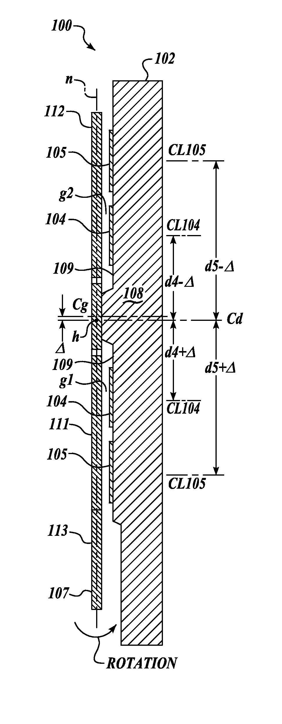
[0045]The present invention embodied as a capacitive acceleration-sensing device of either the mid-pendulum hinged or “teeter-totter” type or the cantilevered “bending beam” type both fabricated using known Micro-Electro-Mechanical System (MEMS) or High aspect ratio MEMS (HIMEMS) technology and having effective portions of one or more excitation and feedback electrodes positioned relative to a pendulous acceleration sensing element as a function of a fulcrum or hinge axis h that is located at a dynamic centerline Cd of a flexure from which the acceleration sensing element is pendulously suspended, where the dynamic centerline Cd is at the center of an effective bending portion of the deflected flexure as measured relative to an undeflected neutral axis n of the flexure. The dynamic centerline Cd is shifted relative to the geometric centerline Cg of the relaxed or undeflected flexure.

[0046]Accordingly, as illustrated in the F...


PUM


Abstract

A Micro Electro-Mechanical System (MEMS) acceleration sensing device formed of a silicon substrate having a substantially planar surface; a pendulous sensing element having a substantially planar surface suspended in close proximity to the substrate planar surface; a flexure suspending the sensing element for motion relative to the substrate planar surface, the flexure having a both static geometric centerline and a dynamic centerline that is offset from the static geometric centerline; and a metal electrode positioned on the substrate surface for forming a capacitor with the pendulous sensing element, the metal electrode being positioned as a function of the dynamic centerline of the flexure.

Description

FIELD OF THE INVENTION[0001]The present invention relates to Micro Electro-Mechanical System (MEMS) sensor devices and methods, and in particular to accelerometer sensor devices and methods based on capacitive pick-off and electrostatic rebalance.BACKGROUND OF THE INVENTION[0002]Sensor devices, including accelerometers, based on capacitive pick-off and electrostatic closed-loop rebalance of out of plane pendulous masses that use single or multiple stacked parallel plates for pick-off are generally well known.[0003]FIGS. 1, 2 and 3 illustrate, in accordance with prior art, a capacitive pick-off sensor constructed as a conventional mid-pendulum hinged or “teeter-totter” type accelerometer having the suspending flexure positioned intermediate the acceleration sensing element, wherein FIG. 1 is an exploded dynamic side view of the sensor, FIG. 2 is a static plan view, and FIG. 3 is a static sectional side view taken along a longitudinal axis L of the accelerometer of FIG. 2. Such device...

Claims


Application Information

Patent Timeline
Patent Type & Authority Patents(United States)
IPC IPC(8): G01P15/125G01P15/00G01P15/08
CPCG01P15/0802G01P15/125H01G5/18H01G5/40
Inventor MALAMETZ, DAVID L.
Owner HONEYWELL INT INC
Why Eureka
Try Eureka