Turbine shroud asymmetrical cooling elements

a turbine shroud and cooling element technology, applied in the direction of liquid fuel engines, machines/engines, efficient propulsion technologies, etc., can solve the problems of difficult cooling, limited blade life, and abrasion wear, so as to reduce local pressure gradient, and reduce the degree of circumferential hot streaking

Active Publication Date: 2006-12-12
GENERAL ELECTRIC CO
View PDF6 Cites 39 Cited by
  • Summary
  • Abstract
  • Description
  • Claims
  • Application Information

AI Technical Summary

Benefits of technology

[0014]The turbine shroud assembly and its asymmetrical cooling elements, such as shroud segments and baffles reduce the degree of circumferential hot streaking due to their location relative to static turbine nozzle airfoils. The asymmetrical cooling elements reduce the degree of circumferential hot streaking due to their location in wake regions from pressure wakes from upstream turbine nozzle airfoils. The asymmetrical cooling elements locally tailor film and convective cooling in wake regions of the static component by reducing local pressure gradients and, thus, increase film cooling air flow in the wake regions.
[0015]The asymmetrical cooling elements reduce heating due to the pressure wakes causing reduced leakage flow of cooling air between a front face of the shroud and the upstream nozzle in the high pressure areas. Thus the asymmetrical cooling elements reduce or eliminate local hot regions and prevent or delay oxidation and eventual burn through of the part and also they can prevent or delay premature failure of the part and / or high scrap rates at overhaul. The asymmetrical cooling elements provide a turbine shroud cooling system that accommodates circumferential heating gradients while minimizing the amount of cooling airflow, loss of engine efficiency, and fuel consumption.

Problems solved by technology

However, due to differential thermal expansion and contraction of the rotor blades and surrounding turbine shroud, the blade tips occasionally rub against the inner surface of the shroud causing abrasion wear.
Since the blade tips are at the radially outermost end of the rotor blades and are directly exposed to the hot combustion gases, they are difficult to cool and the life of the blade is thereby limited.
A relatively large amount of impingement cooling air is generally required for effective impingement cooling which decreases engine efficiency.
In a high pressure turbine, the temperatures are not always circumferentially uniform and static components, such as turbine shrouds, in the flowpath can experience hot streaks.
The pressure wakes may also cause leakage flow of cooling air between a front face of the shroud and the upstream nozzle to be reduced in the high pressure areas, further increasing the local temperature of the shroud leading edge in this region.
This effect may be particularly severe with new high performance nozzle designs incorporating 3-D aerodynamics and which are characterized by more severe pressure gradients at the flowpath edges.
Local hot regions can result in oxidation and eventual burn through of the part.
This can result in premature failure of the part and / or high scrap rates at overhaul.

Method used


Image

  • Turbine shroud asymmetrical cooling elements
  • Turbine shroud asymmetrical cooling elements
  • Turbine shroud asymmetrical cooling elements

Examples


Embodiment Construction

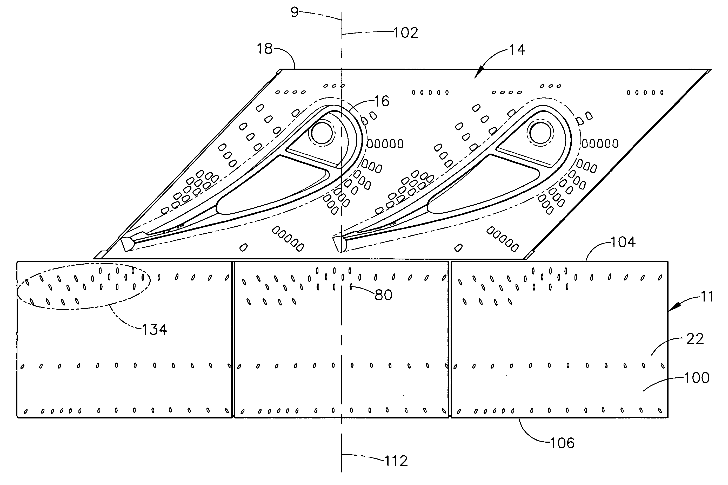
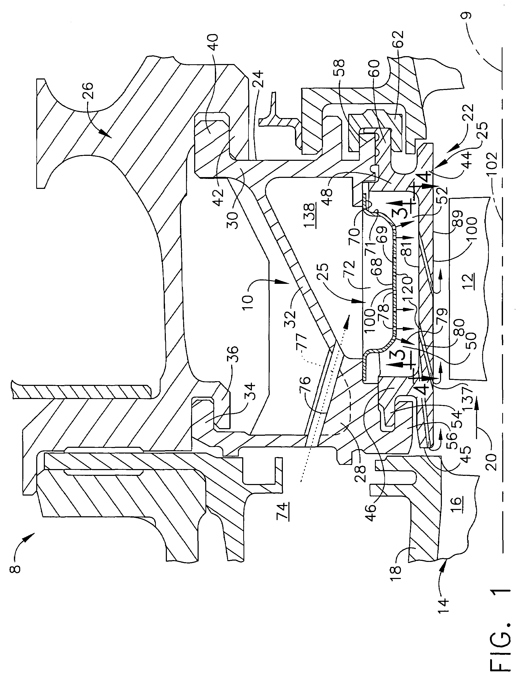
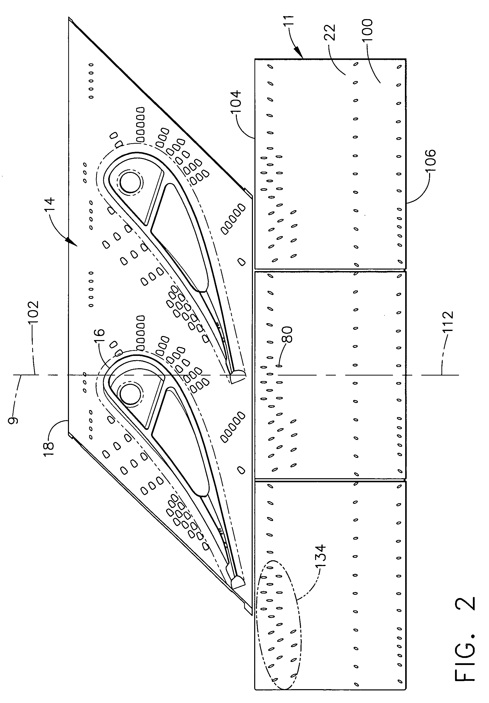
[0021]Illustrated in cross-section in FIG. 1 is a portion of a gas turbine engine high pressure turbine section 8 having a turbine shroud assembly 10 disposed in closely surrounding radial relation with turbine blades 12. A turbine nozzle 14 includes a plurality of fixed vanes 16 affixed to an outer band 18 for directing a core engine gas stream 20 from a combustor (not shown) through the high pressure turbine section. The shroud assembly 10 includes an annular shroud 11 having an annular array of arcuate shroud segments 22 which are held and supported in position by an annular array of arcuate hanger segments 24, all of which are circumferentially disposed about an engine centerline axis 9. The arcuate hanger segments 24 are in turn supported by an engine outer casing 26.

[0022]Each hanger segment 24 includes a forward or upstream rail 28 and an aft or downstream rail 30 and a body panel 32 therebetween. The upstream rail 28 has a rearwardly extending aft flange 34 which radially ov...


PUM


Abstract

A turbine shroud assembly asymmetrical cooling element such as a shroud segment or a baffle includes an arcuate panel. The panel has a plurality of cooling apertures extending through the panel and an axially extending midline of the panel parallel to an axis of rotation of the arcuate panel. A symmetric portion of the cooling apertures have a symmetrical density of aperture inlets that is symmetric with respect to the axially extending midline. An asymmetric portion of the cooling apertures have an asymmetrical density of aperture inlets that is asymmetric with respect to the axially extending midline. One exemplary cooling element includes a high density area of the cooling apertures in the asymmetric portion having a higher density of aperture inlets than in the symmetric portion. A low density area of the cooling apertures in the asymmetric portion has a lower density of aperture inlets than in the symmetric portion of the cooling apertures.

Description

BACKGROUND OF THE INVENTION[0001]1. Field of the Invention[0002]This invention relates generally to gas turbine engines and, more specifically, to cooled turbine shrouds and impingement baffles that cool the shrouds.[0003]2. Description of Related Art[0004]In a gas turbine engine, air is pressurized in a compressor, mixed with fuel in a combustor, and ignited for generating hot combustion gases which flow downstream through one or more turbine stages which extract energy therefrom. A high pressure turbine (HPT) first receives the combustion gases from the combustor and extracts energy therefrom for powering the compressor. A low pressure turbine (LPT) downstream of the HPT extracts additional energy for providing output energy used for powering a fan disposed upstream of the compressor in a typical aircraft gas turbine engine application. In an industrial or a marine gas turbine engine, the LPT drives an output shaft for powering a generator or propellers of a ship. Shafts may also ...

Claims


Application Information

Patent Timeline
Patent Type & Authority Patents(United States)
IPC IPC(8): F01D25/12F01D25/14F01D9/04F01D11/08F01D25/24F02C7/18F02C7/28
CPCF01D9/04F01D11/08F01D25/12Y02T50/676F05D2260/201F05D2260/202F05D2240/81Y10S165/908Y02T50/60
Inventor LOWE, CEDRIC CARLTONPOWIS, ANDREW CHARLESCLARKE, JONATHAN PHILIP
Owner GENERAL ELECTRIC CO
Why Eureka
Try Eureka