
Magnetic rotating motor generator

a technology of rotating motors and generators, which is applied in the direction of generators/motors, machines/engines, mechanical equipment, etc., can solve the problems of increased manufacturing costs, increased manufacturing costs, and insufficient water supply

Active Publication Date: 2006-12-12
FOREST PINE ELECTRIC
View PDF18 Cites 16 Cited by
  • Summary
  • Abstract
  • Description
  • Claims
  • Application Information

AI Technical Summary

Benefits of technology

This solution enables clean, efficient, and cost-effective power generation with reduced noise and heat, achieving a high percentage of input power regeneration and providing semipermanent drive capabilities without increasing manufacturing costs.

Problems solved by technology

In the case of water power generation, dams for rotating hydraulic turbines must be constructed, resulting in environmental destruction.
The amount of water is not always sufficient.
Further, sediment is deposited on the dams and thus the dams are not used permanently.
In the case of wind power generation, since the wind power which is a natural phenomenon is utilized, only costs for installing generators are required.
Nevertheless, since the wind power generation depends on the natural phenomenon, it has a problem such as instable ensuring of energy.
Further, thermal power generation pollutes air because of combustion of oil or coal and has problems including inferior thermal efficiency and encouragement of global warming.
Nuclear power generation requires substantial costs for constructing facilities and has problems about safety.
As described above, the conventional power generation apparatuses require substantial costs for constructing facilities and have problems including environmental pollution, air pollution, heat generation and stable supply of the energy.
Although a single rotator structure conventionally has functions as a motor and as a generator, it cannot exhibit the function of a generator while exhibiting the function of a motor, and vice versa.

Method used


Image

  • Magnetic rotating motor generator
  • Magnetic rotating motor generator
  • Magnetic rotating motor generator

Examples


examples

[0055]A description will be given of examples that power generation is performed by rotating a sirocco fan with a motor generator formed of four permanent magnets and four electromagnets as illustrated in FIG. 9. Coils for the four electromagnets have a diameter φ of 0.6 mm and the number “n” of windings is “600”. Batteries (Yuasa NP7-12) with 12V each are serially connected in order to supply 24V of voltage.

[0056](1) In an example illustrated in FIG. 14, a load Ro is 0.2Ω, an input voltage is B V and an input electric current is C A. The motor generator performs 930 rpm of rotation as a motor and outputs D V of output voltage and E A of output electric current.

[0057](2) In an example illustrated in FIG. 15, the load Ro is 0.1Ω, the input voltage is F V and the input electric current is G A. The motor generator performs 900 rpm of rotation as a motor and outputs H V of output voltage and I A of output electric current.

[0058](3) FIG. 16 illustrates an example in which output power is...


PUM


Abstract

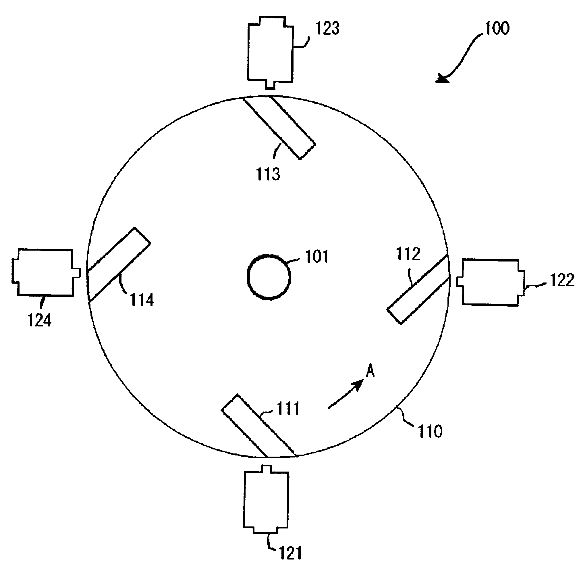
A magnetic rotating motor generator of the present invention comprises a rotating portion which is made of a non-magnetic substance whose periphery is provided with a group of permanent magnets tilted at a predetermined angle in an embedded manner; a group of electromagnets that are disposed adjacently to the rotating portion so as to oppose the group of permanent magnets; a positional sensor for detecting positions of the group of permanent magnets; a controller for applying an electric current to the electromagnet on the basis of a detected signal from the positional sensor; and a power generating section for obtaining power from a coil of the electromagnet. A rotation mode and a power generation mode are repeated, so that power generation is performed while a function as a motor is exhibited.

Description

BACKGROUND OF THE INVENTION[0001]1. Field of the Invention[0002]The present invention relates to a magnetic rotating motor generator that a motor which is subject to magnetic rotational drive and semipermanently performs predetermined work (e.g., rotation of a fan or drive of a mechanical shaft) in a rotation mode and, at the same time, has a power generation mode for performing power generation, and power regeneration is possible.[0003]2. Description of the Related Art[0004]Conventionally, power is obtained by rotating a generator by using water power, wind power, thermal power and nuclear power as energy. In the case of water power generation, dams for rotating hydraulic turbines must be constructed, resulting in environmental destruction. The amount of water is not always sufficient. Further, sediment is deposited on the dams and thus the dams are not used permanently. In the case of wind power generation, since the wind power which is a natural phenomenon is utilized, only costs...

Claims


Application Information

Patent Timeline
Patent Type & Authority Patents(United States)
IPC IPC(8): H02K47/04F03G7/10H02K53/00H02N11/00
CPCH02K53/00
Inventor MINATO, KOHEIMINATO, NOBUE
Owner FOREST PINE ELECTRIC
Learn More