Magnetic head with electro-lapping guide

a magnetic head and guide technology, applied in the field of thin film magnetic heads, to achieve the effect of high accuracy

Inactive Publication Date: 2006-12-12
HITACHI GLOBAL STORAGE TECH JAPAN LTD +1
View PDF17 Cites 23 Cited by
  • Summary
  • Abstract
  • Description
  • Claims
  • Application Information

AI Technical Summary

Benefits of technology

[0018]According to another aspect of the invention, there is provided a thin-film magnetic head, wherein the first magneto-resistive effect element and the second magneto-resistive effect element include a first magneto-resistive effect film and a second magneto-resistive effect film, respectively, wherein each film is sandwiched by electrodes, and an end of each of the magneto-resistive effect films is exposed to the slider surface, and wherein the two electrode sets and the magneto-resistive effect films are formed in the same geometric shape.
[0019]According to still another aspect of the invention, there is provided a thin-film magnetic head, wherein the first magneto-resistive effect element has a first magneto-resistive effect film formed between a lower shield and an upper shield, and these components are stacked on the substrate, and wherein the second magneto-resistive effect element is formed in the plane in which the first magneto-resistive effect film is formed.
[0020]According to yet another aspect of the invention, there is provided a method of manufacturing a magnetic head, comprising the steps of forming first magneto-resistive effect elements and second magneto-resistive effect elements on a substrate formed with an insulating film, cutting the resulting assembly into a plurality of sliders each containing a first magneto-resistive effect element and a second magneto-resistive effect element, mounting at least a slider on a lapping machine, and lapping independently the surface of each slider perpendicular to the first magneto-resistive effect element

Problems solved by technology

(1) An error in forming an exposure mask used for forming the magneto-resistive effect elements and the electric lapping guide elements on a substrate and the exposure error in the exposure process thereof.
(2) An error caused by the difference in the lapping amount due to the distance between the positions of

Method used


Image

  • Magnetic head with electro-lapping guide
  • Magnetic head with electro-lapping guide
  • Magnetic head with electro-lapping guide

Examples


Embodiment Construction

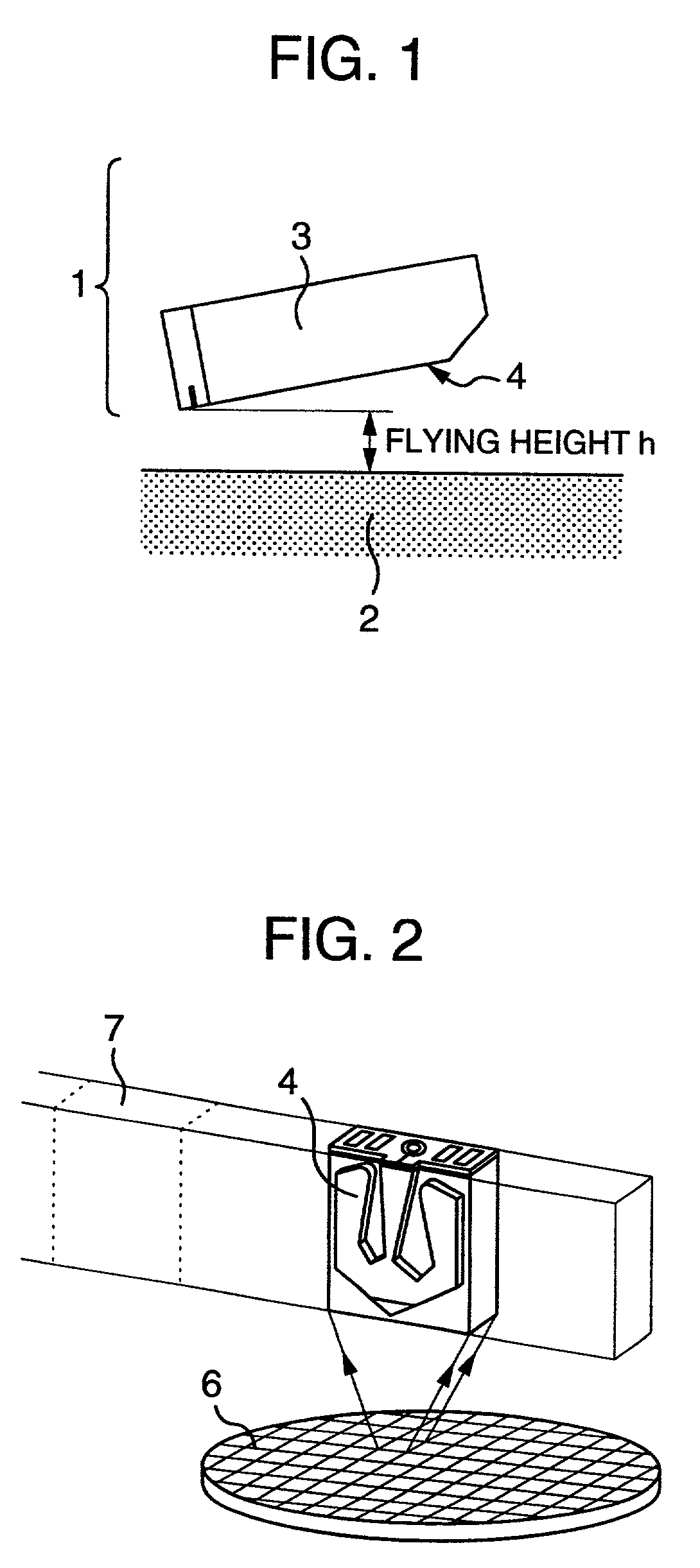
[0040]First, an outline of a magnetic disk drive will be explained. FIG. 1 is a diagram for explaining the layout of a magnetic head 1 and a disk 2. The magnetic head 1 is configured of a slider 3 and a magneto-resistive effect element 5 formed on the slider 3 and arranged in a plane perpendicular to the slider surface 4. In a magnetic disk drive of CSS (contact start stop) type, the magnetic head 1, or exactly, an end portion of the magneto-resistive effect element 5 is flown by a very small amount over the surface of the disk 2 utilizing the dynamic pressure caused by the rotation of the disk 2 making up a magnetic recording medium thereby to write (record) or read (reproduce) information into or from the disk 2. In the process, the gap between the surface of the disk 2 and the magneto-resistive effect element 5 is defined as the flying height h. The smaller the flying height h, the higher the recording or reproduction efficiency.

[0041]The magnetic head 1 will be explained with re...


PUM

PropertyMeasurementUnit
Electrical resistanceaaaaaaaaaa
Magnetismaaaaaaaaaa

Abstract

A thin-film includes an inductive element and a first and second magneto-resistive effect elements in which the first and second magneto-resistive effect elements are arranged in proximity to each other on a substrate, and one surface of the substrate perpendicular to the surface formed with the first and second magneto-resistive effect elements constitutes a slider surface, thereby providing appropriate hight of the magneto-resistive effect elements.

Description

BACKGROUND OF THE INVENTION[0001]The present invention relates to a thin-film magnetic head having magneto-resistive effect elements, or in particular to a structure and a method of manufacturing a thin-film magnetic head for controlling the height of the magneto-resistive effect elements with high accuracy.[0002]In recent years, the size of the magnetic disk drive has been ever on the decrease with the capacity thereof even on the increase, and small-sized magnetic disk drives using a 3.5-inch disk and 2.5-inch disk, respectively, are now the main stream. Among the magnetic heads used for these small-sized magnetic disk drives, the magnetic induction head of which the read output depends on the rotational speed of the disk has too small a disk rotational speed to produce a sufficient read output. With a magneto-resistive effect head using a magneto-resistive effect element having a resistance value changing with the magnetic field, on the other hand, the read output is not dependen...

Claims


Application Information

Patent Timeline
IPC IPC(8): G11B5/33G11B5/10G11B5/187G11B5/31G11B5/39G11B5/48G11B5/60
CPCG11B5/3173G11B5/3967G11B5/6005G11B5/3169G11B5/102G11B5/1871G11B5/3106G11B5/3166Y10T29/49041G11B5/488
Inventor YAMAKURA, HIDEOTAMURA, TOSHIOTANAKA, KOJI
Owner HITACHI GLOBAL STORAGE TECH JAPAN LTD
Why Eureka
Try Eureka