Peripheral component with high error protection for stored programmable controls

peripheral component technology, applied in the field of interface modules having a high level of error immunity for programmable logic controllers, can solve the problems of transferring extensive monitoring tasks, performing this task, and possible presupposition of atmosphere, so as to increase the error immunity of a programmable logic controller, reduce programming complexity, and increase the security against failure of the interface block itsel

Inactive Publication Date: 2006-12-12
SIEMENS AG
View PDF19 Cites 9 Cited by
  • Summary
  • Abstract
  • Description
  • Claims
  • Application Information

AI Technical Summary

Benefits of technology

[0028]In another test mode, one channel is used for signal transmission and the other is meanwhile subjected to a test by outputting a test signal and reading it in again, the signal value which is output and the signal value which is read in being subtracted from one another, and the result of the subtraction finally being compared with at least one prescribed limit value in order to identify an error if there is a relatively large discrepancy. While parallel operation of the two channels and comparison of their output signals make it possible to establish whether an error has actually occurred in one of these two channels, the latter test mode even makes it possible to ascertain which of the two channels is faulty. This is achieved by connecting the channel which is to be examined as part of a signal transmission loop, and comparing the output signal from this loop with its input signal allows a malfunction in the channel block in question to be diagnosed if there is an identifiable discrepancy. In such a case, this channel can be selectively disconnected, and then just the remaining channel can be used temporarily until the fault has been eliminated as a result of an alarm triggered by the error message.
[0029]To allow early identification of an error which has occurred, the test mode should be repeated at short intervals of time, with first one channel and then the other being respectively tested, and the respective other one undertaking the signal transmission in the meantime. In the extremely unlikely situation in which both channel blocks become damaged at the same time, comparison of the output signals might possibly establish no error if, by way of example, both output signals adopt zero voltage at the same time. However, this situation can be prevented or identified by regularly testing the absolute operability of the channel blocks. For this reason, at least one of the two channel blocks should be examined at short intervals of time with regard to its absolute operability. Since simultaneous failure of both channel blocks is an extremely rare event, these absolute operation tests can be carried out at relatively long intervals of time, for example approximately once per second. Provided that the channel blocks connected in parallel are not compared during normal operation, the flow of data between the two channel blocks should be changed over at correspondingly short intervals of time and, in the meantime, at least one test on the channel block which has not been required up until then should be carried out in each case.
[0030]Optimum results can be attained if a data processing module undertakes the evaluation of the test results (comparison of the output signals on the two channels and of the read-in test result with the output test result). During correct operation, the output signals from both channel blocks operated in parallel can always be compared in the same data processing module; the control of the test channel block and the comparison between the respective test loop's input signal and output signal can also be transferred to the data processing module for the absolute value tests which are to be performed alternately. This reduces the programming complexity, since a unique master-slave configuration is obtained, where control commands are always sent from the master module to the slave module and information is always sent in the opposite direction.
[0031]Correct data interchange with the central processor unit for the programmable logic controller takes place by virtue of a data processing module, preferably the one undertaking evaluation, communicating with the central control unit via a data interface. The interface module can be used in various respects in order to increase the error immunity of a programmable logic controller. Merely a plant having just one central processor unit and a communication bus has increased security against failure of the interface block itself. The use of particularly secure data lines and / or the use of particularly secure data formats and / or a reduction in the data transfer rate can likewise achieve an increase in security. According to standard, this communication takes place with one of the two data processing blocks in the interface block. The central processor unit can also use this block to request the current error status for the two channel blocks. For this purpose, it is therefore advantageous to use that block which also controls the test procedure at the same time, since in such a case data transfer from the master module to the slave module is not necessary.

Problems solved by technology

The design of control loops had resulted in feedback of process signals, and this tendency finally resulted in the transfer of extensive monitoring tasks to programmable logic controllers.
However, it can only perform this task if it is certain to work correctly itself even, and specifically, upon the occurrence of malfunctions in the plant.
Although the use of microelectronics in millions of wristwatches, household appliances, aircraft and vehicles shows that the greatest risk when operating an electronic circuit is probably failure of the supply voltage, particularly a drop in the battery voltage, it must not be forgotten that industrial plants are operated on a crude basis and only rarely is it possible to presuppose an atmosphere which is entirely free of vapors, gases and other chemicals.
In such a case, an error can theoretically occur in all the components, i.e. both in the central processor unit and in the connected components, and also on the communications line connecting them to one another.
While the first two sources of error can be prevented, or can be reduced to an extremely minimal residual risk, for critical processes by increasing the availability, for example by using a second central processor unit connected in parallel and / or a second communication bus operated in parallel, duplication of all other components in most application instances would entail a substantial level of additional involvement, and the enormous increase in complexity would additionally mean that it would instead even impose the risk of additional sources of error as a result of wiring or setting errors.

Method used


Image

  • Peripheral component with high error protection for stored programmable controls
  • Peripheral component with high error protection for stored programmable controls
  • Peripheral component with high error protection for stored programmable controls

Examples


Embodiment Construction

[0039]Reference will now be made in detail to the preferred embodiments of the present invention, examples of which are illustrated in the accompanying drawings, wherein like reference numerals refer to like elements throughout.

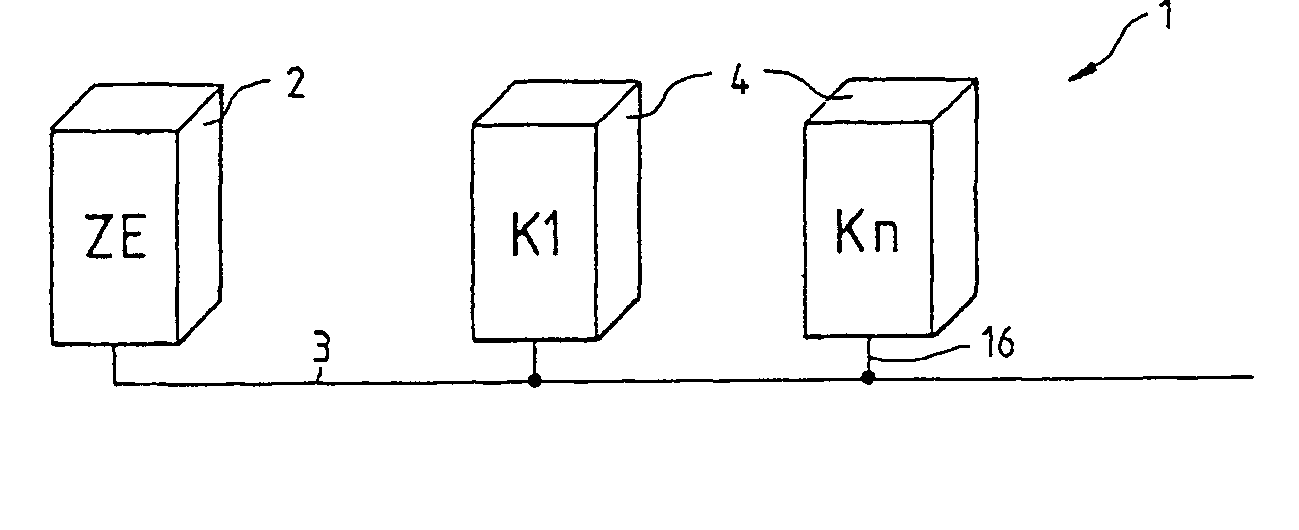
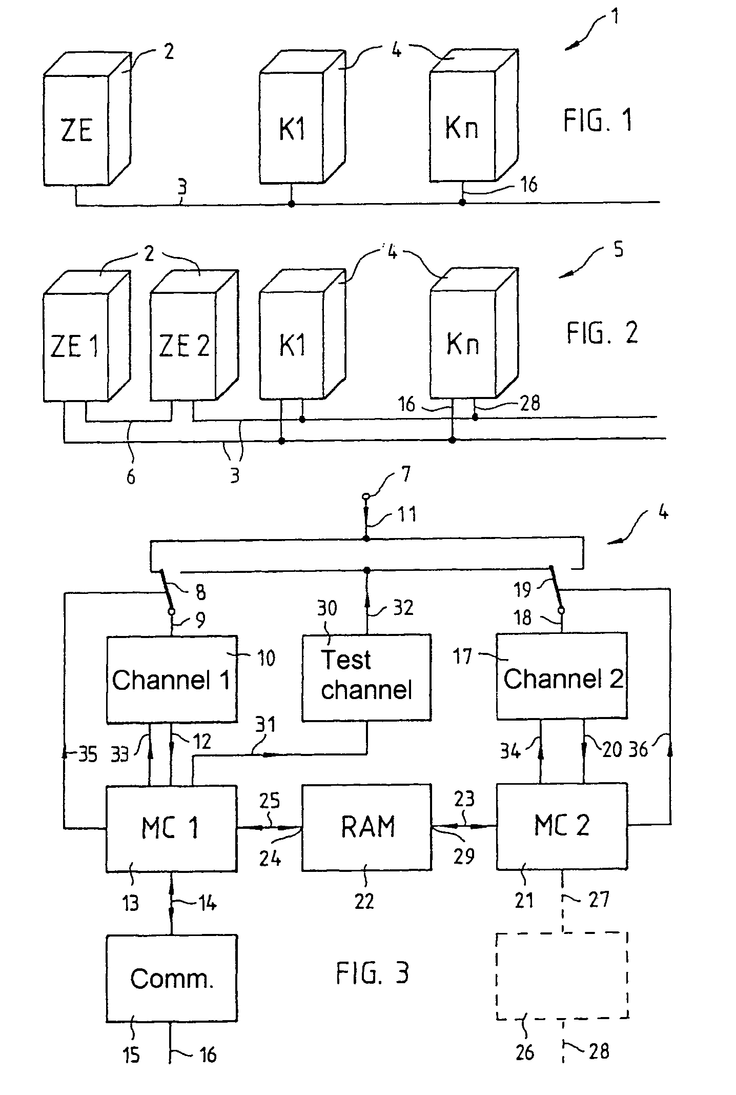
[0040]The programmable logic controller 1 shown in FIG. 1 comprises a central processor unit 2 of fail-safe design to which n components 4, at least one of which is of fail-safe design, are connected via a communication bus 3 operated in a fail-safe manner. The fail-safe components 2–4 form a continuous, security-related chain, with information being detected by the fail-safe component 4, being transferred to the central processor unit 2 via the communication bus 3 with a high level of security, and being logically combined therein in order to obtain control commands which can be used to prompt a reaction from an actuator in the plant via the communication bus 3 and an interface component 4 which is in turn fail-safe. The high level of error immunity in the i...


PUM


Abstract

The invention relates to a peripheral component with high error protection for stored programmable controls. The invention relates particularly to an analog-input circuit with at least two channels substantially identical in design, for parallel signal input and/or output, which are parallel connected and/or parallel connectable in the region of the peripheral interface. Said analog-input circuit also comprises at least one data processing component (μP or μC) for testing the channels without any disruption of the data flows.

Description

CROSS REFERENCE TO RELATED APPLICATIONS[0001]This application is based on and hereby claims priority to PCT Application No. PCT / DE01 / 01885 filed on May 17, 2001, German Application No. 100 24 479.3 filed on May 18, 2000, and German Application No. 100 35 174.3 filed on Jul. 19, 2000, the contents of which are hereby incorporated by reference.BACKGROUND OF THE INVENTION[0002]The invention relates to an interface module having a high level of error immunity for programmable logic controllers, particularly to an analog-input circuit.[0003]U.S. Pat. No. 5,508,910 discloses a redundant analog input / output system having two identical analog input / output units, with in respective input / output unit being in operating mode and the respective other one being in monitor mode. Each analog input / output unit has a microcomputer, two D / A converters and a D / A converter. In a fault situation, the respective microcomputer for one analog input / output unit switches itself to monitor mode and switches t...

Claims


Application Information

Patent Timeline
Patent Type & Authority Patents(United States)
IPC IPC(8): G06F11/00G05B19/042G06F11/16G06F11/20
CPCG05B19/0425G06F11/1616G06F11/1633G06F11/165G06F11/221G05B2219/24174G05B2219/24197G06F11/2007
Inventor VATH, JOACHIM
Owner SIEMENS AG
Why Eureka
Try Eureka