
Vehicle control apparatus and method

a technology of vehicle control and control apparatus, which is applied in the direction of engine-driven generators, machines/engines, transportation and packaging, etc., can solve the problems of increasing electric power consumption, reducing load, and reducing the efficiency of electric power consumption, so as to reduce load and prevent drastic engine speed increase

Inactive Publication Date: 2006-12-19
SUZUKI MOTOR CORP
View PDF17 Cites 21 Cited by
  • Summary
  • Abstract
  • Description
  • Claims
  • Application Information

AI Technical Summary

Benefits of technology

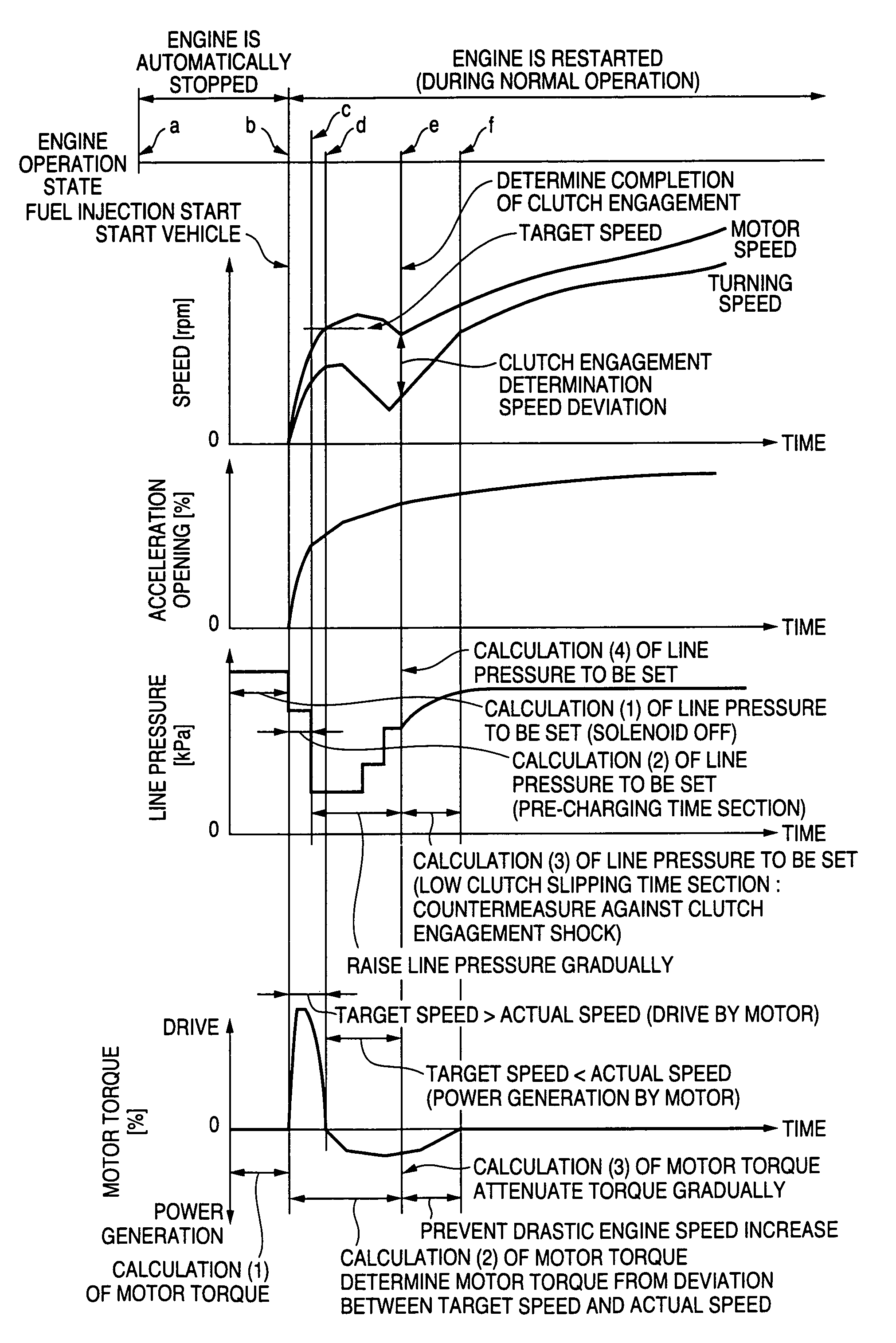
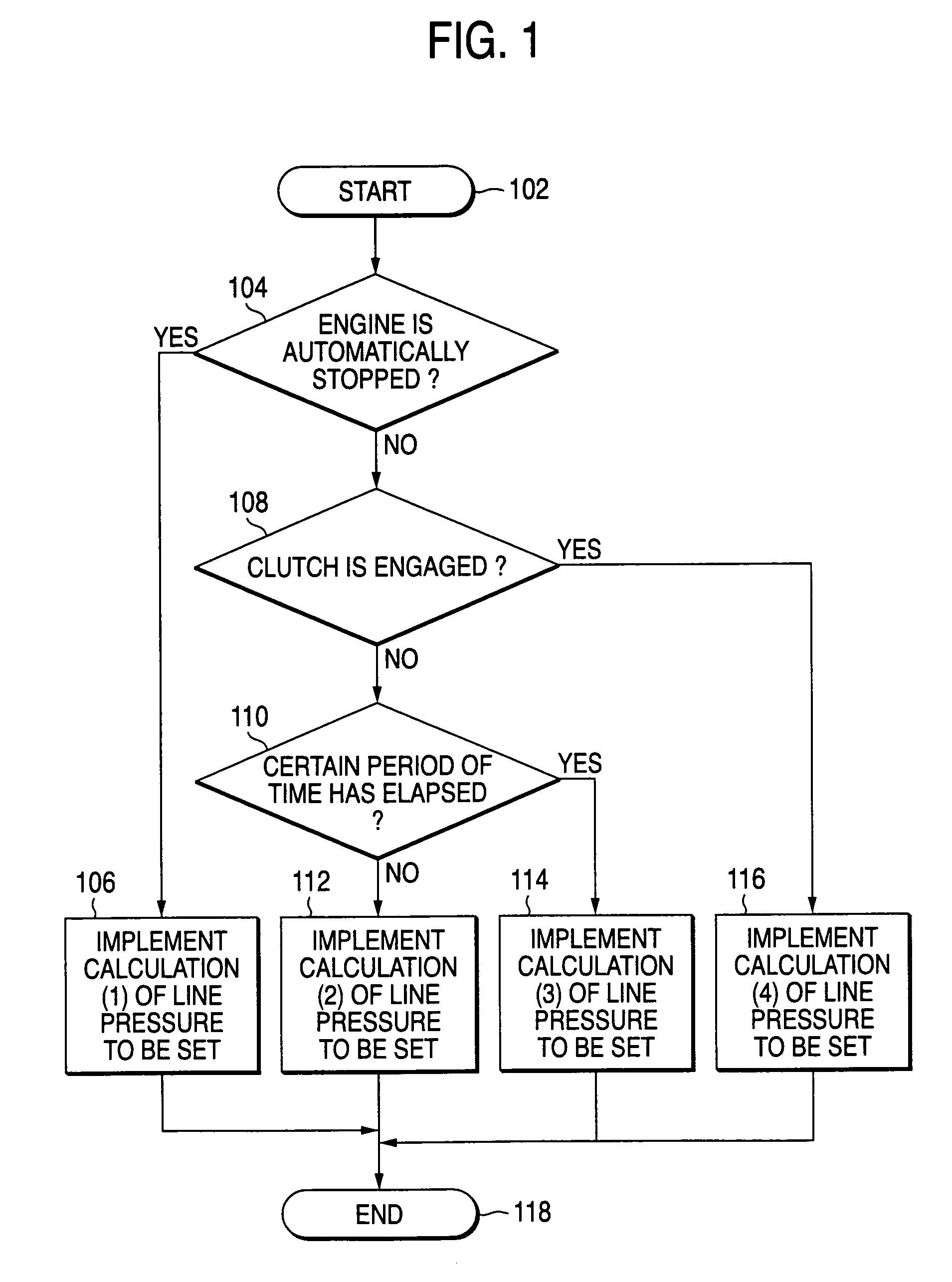
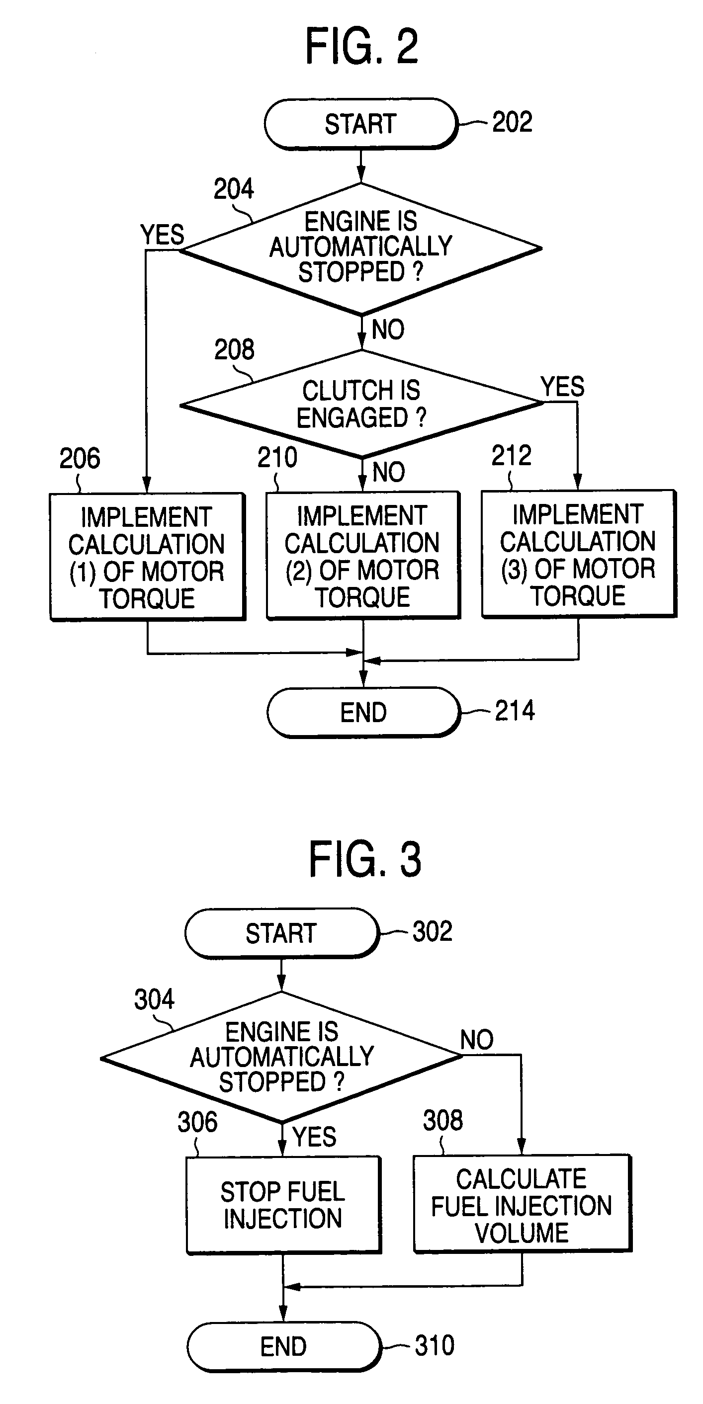
[0007]According to the invention, when the engine is put in an automatically restarted state from an automatic stopped state, by implementing not only a line pressure control for controlling the line pressure of the automatic transmission but also a motor assist control for controlling the assist amount by the electric generator a reduction in load applied to the engine can be avoided through the control of the oil pressure of the automatic transmission and control of the drive of the electric generator when the vehicle is attempted to be started from rest after the engine has been restarted, whereby the drastic engine speed increase can be prevented even if no electrically operated hydraulic pump is provided separately, thereby making it possible to have a simple construction. In addition, according to the invention, the engagement shock that is caused when the clutch of the automatic transmission is engaged can be reduced, and moreover, the power consumption can be reduced, thereby making it possible to increase the attractiveness of the vehicle as a product.

Problems solved by technology

In case vehicles have to stop like that, since fuel continues to be consumed as long as the engine is running, there is caused a drawback that the fuel consumption gets worse.
This has been causing a problem that when a vehicle is attempted to move from a standstill after the engine is restarted, there is caused a delay in raising the oil pressure that is sent to the automatic transmission, and less load is applied to the engine to thereby cause a drastic engine speed increase, while when the oil pressure to the engine is raised thereafter and the clutch is engaged, an engagement shock which is brought about by the engagement of the clutch is caused in the vehicle.
In addition, although there has been proposed a method in which an electric oil pump is provided separately, so that the electric oil pump is driven to produce an oil pressure for engagement of the clutch while the engine is automatically stopped (JP-A-8-14076), this method has caused a drawback that electric power consumption is increased.

Method used


Image

  • Vehicle control apparatus and method
  • Vehicle control apparatus and method
  • Vehicle control apparatus and method

Examples


Embodiment Construction

[0014]A detailed embodiment of the invention will be described below based on the accompanying drawings. FIGS. 1 to 6 show the embodiment of the invention. In FIG. 5, reference numeral 2 denotes a vehicle enabling the implementation of an automatic stop and restart control, reference numeral 4 an engine (E / G) installed in the vehicle 2, reference numeral 6 an electric generator (motor (M) / generator (G)), and reference numeral 8 an automatic transmission (A / T). The automatic transmission 8 includes a torque converter 10 and a transmission unit 12 and is controlled hydraulically. While not shown, the torque converter 10 is made up of a turbine, a pump impeller and a stator. While not shown, the transmission unit 12 includes planetary gears or the like.

[0015]The electric generator 6 is connected to an engine output shaft 14 of the engine 4. This electric generator 6 communicates with the torque converter 10 of the automatic transmission 8 via an input shaft 16. The torque converter 10 ...


PUM


Abstract

A controller is provided for implementing a line pressure control for controlling a line pressure for an automatic transmission and a motor assist control for controlling an assist amount by an electric generator when an engine is put into an automatically restarted state from an automatically stopped state.

Description

BACKGROUND OF THE INVENTION[0001]The present invention relates to a vehicle control apparatus and method, and more particularly to a vehicle control apparatus for a vehicle in which an electric generator and an automatic transmission including a hydraulically controlled clutch are provided along a power transmission system or a drive train, in that an engine is controlled so as to be automatically stopped and restarted.[0002]It frequently happens that vehicles have to stop while being driven in towns and at intersections. In case vehicles have to stop like that, since fuel continues to be consumed as long as the engine is running, there is caused a drawback that the fuel consumption gets worse. With a view to solving the drawback, there has been proposed a vehicle provided with an automatic stop and restart system for improving the fuel consumption by automatically stopping the engine when the vehicle stops temporarily and restarting the engine when the vehicle starts off (JP-A-6-25...

Claims


Application Information

Patent Timeline
Patent Type & Authority Patents(United States)
IPC IPC(8): B60K6/00B60W20/00B60K6/485B60K6/54B60L50/16B60W10/00B60W10/02B60W10/04B60W10/06B60W10/08B60W10/10F02D17/00F02D29/00F02D29/02F02D29/06F16H59/38F16H59/42F16H61/00F16H61/02F16H63/50
CPCB60K6/485B60K6/54B60W10/06B60W10/08B60W10/10B60W20/00F16H61/0021B60W30/192B60L2240/421B60W2710/0616B60W2710/081F16H2059/385F16H2312/14Y02T10/6226Y02T10/6286Y02T10/642B60W2510/108Y02T10/62Y02T10/64B60K2006/268B60W30/18027B60W20/40
Inventor NODA, NORIHIROMORI, TATSUJI
Owner SUZUKI MOTOR CORP
Features
  • Generate Ideas
  • Intellectual Property
  • Life Sciences
  • Materials
  • Tech Scout
  • Unparalleled Data Quality
  • Higher Quality Content
  • 60% Fewer Hallucinations
Learn More