

Surface coated cemented carbide cutting tool having hard coating layer exhibiting excellent wear resistance in high speed machining
a cemented carbide and cutting tool technology, applied in the field of cemented carbide cutting tools, can solve the problems of shortening the operation life of the tool, and achieve the effects of increasing the strength and toughness of the layer itself, reducing the wear resistance of the layer, and increasing the strength and toughness
- Summary
- Abstract
- Description
- Claims
- Application Information
AI Technical Summary
Benefits of technology
Problems solved by technology
Method used
Image

Examples
example 1
[0053]Ingredient powders, i.e., WC powder, TiC powder, ZrC powder, VC powder, TaC powder, NbC powder, Cr3C2 powder, TiN powder, TaN powder, and Co powder, all of which have an average grain size in a range from 1 to 3 μm, were prepared and mixed in accordance with compounding ratios as presented in TABLE 1. The ingredient powders were mixed under wet conditions using a ball mill for 72 hours, were dried, and were compacted under pressure of 100 MPa so as to form a green compact. The green compact was held in a vacuum (pressure of 6 Pa) at a predetermined temperature of 1400° C. for 1 hour so as to be sintered. After sintering, the honing of R: 0.05 is given to the part of the cutting edge so that cemented carbide substrates made from the WC base cemented carbide A1–A10 meeting ISO CNMG120408 geometrical configuration of insert were made, respectively.
[0054]Also, ingredient powders, i.e., TiCN (wherein TiC / TiN=50 / 50 by mass ratio) powder, Mo2C powder, ZrC powder, NbC powder, TaC powd...
example 2
[0085]Ingredient powders, i.e., middle coarse grain WC powder having 5.5 μm for the average particle diameter, fine WC powder having 0.8 μm for the average particle diameter, TaC powder having 1.3 μm for the average particle diameter, NbC powder having 1.2 μm for the average particle diameter, ZrC powder having 1.2 μm for the average particle diameter, Cr3C2 powder having 2.3 μm for the average particle diameter, VC powder having 1.5 μm for the average particle diameter, (Ti,W)C powder having 1.0 μm for the average particle diameter, Co powder having 1.8 μm for the average particle diameter were prepared and mixed in accordance with compounding ratios as presented in TABLE 9. Furthermore, wax was added to the ingredient powders and these were mixed in acetone using a ball mill for 24 hours, dried under a reduced pressure, and were compacted under pressure of 100 MPa so as to form a green compact. The green compact was heated up to a predetermined temperature in a range from 1370 to ...
example 3
[0108]The three types of sintered round rod each having a diameter of 8 mm (for cemented carbide substrates a–c), 13 mm (for cemented carbide substrates d–f), and 26 mm (for cemented carbide substrate g, h), respectively, which were made through the process as described in Example 2, were used again and further subjected to a grinding work so that cemented carbide substrates (twist drills) from “a′” to “h′” were made in which each substrate has dimensions, i.e., the diameter and the length, of 4 mm×13 mm (cemented carbide substrates a′–c′), 8 mm×22 mm (cemented carbide substrates d′–f′), and 16 mm×45 mm (cemented carbide substrates g′, h′), respectively.
[0109]Next, these cemented carbide substrates (twist drills) a′–h′ were subjected to ultrasonic cleaning in an acetone solvent for the surface, were dried, and set in an ordinary arc ion plating apparatus as shown in FIG. 5, respectively. Then, the crystal orientation hysteresis layer (the (Ti, Al)NC layer) and the hard coating layer...
PUM
| Property | Measurement | Unit |
|---|---|---|
| thickness | aaaaa | aaaaa |
| thickness | aaaaa | aaaaa |
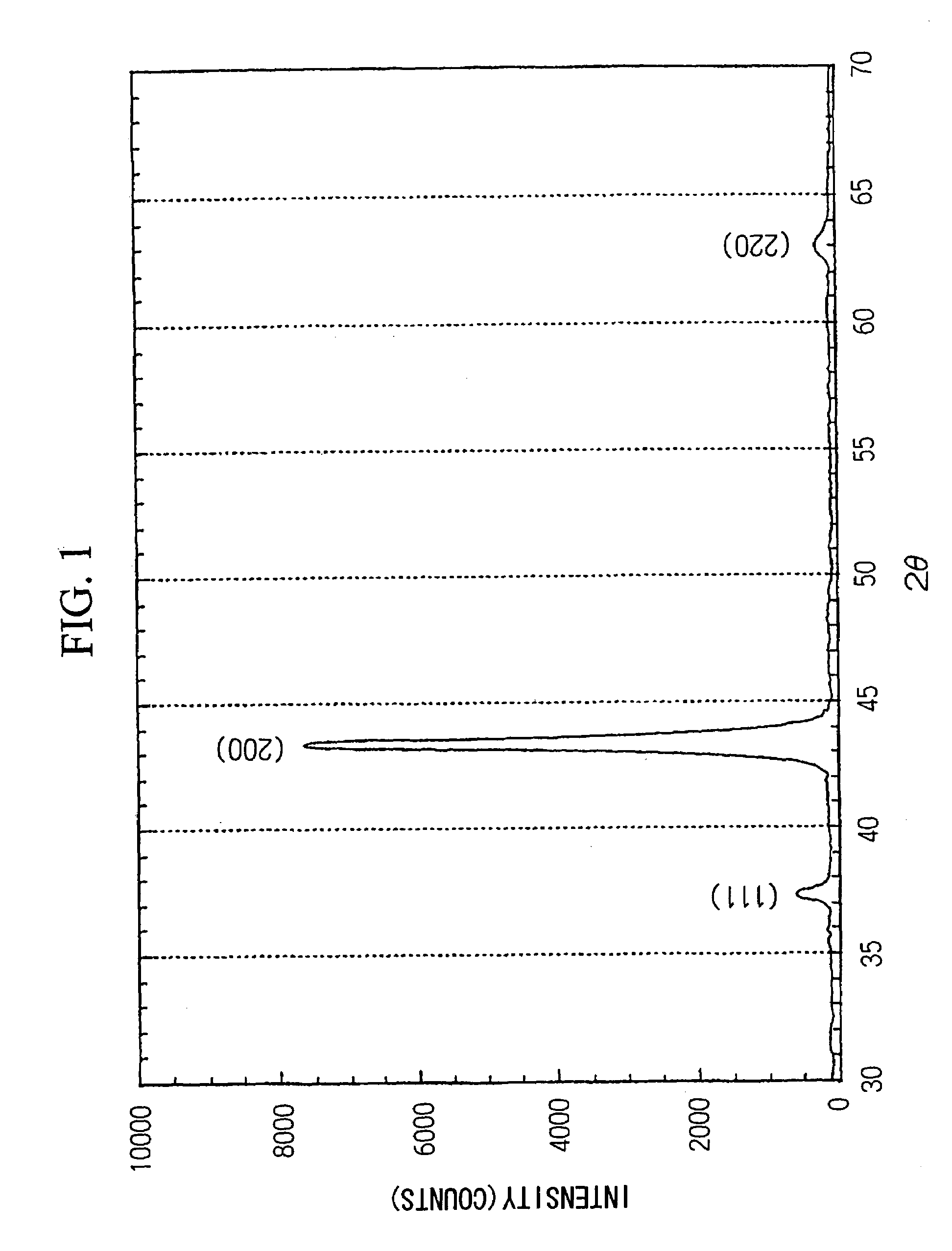
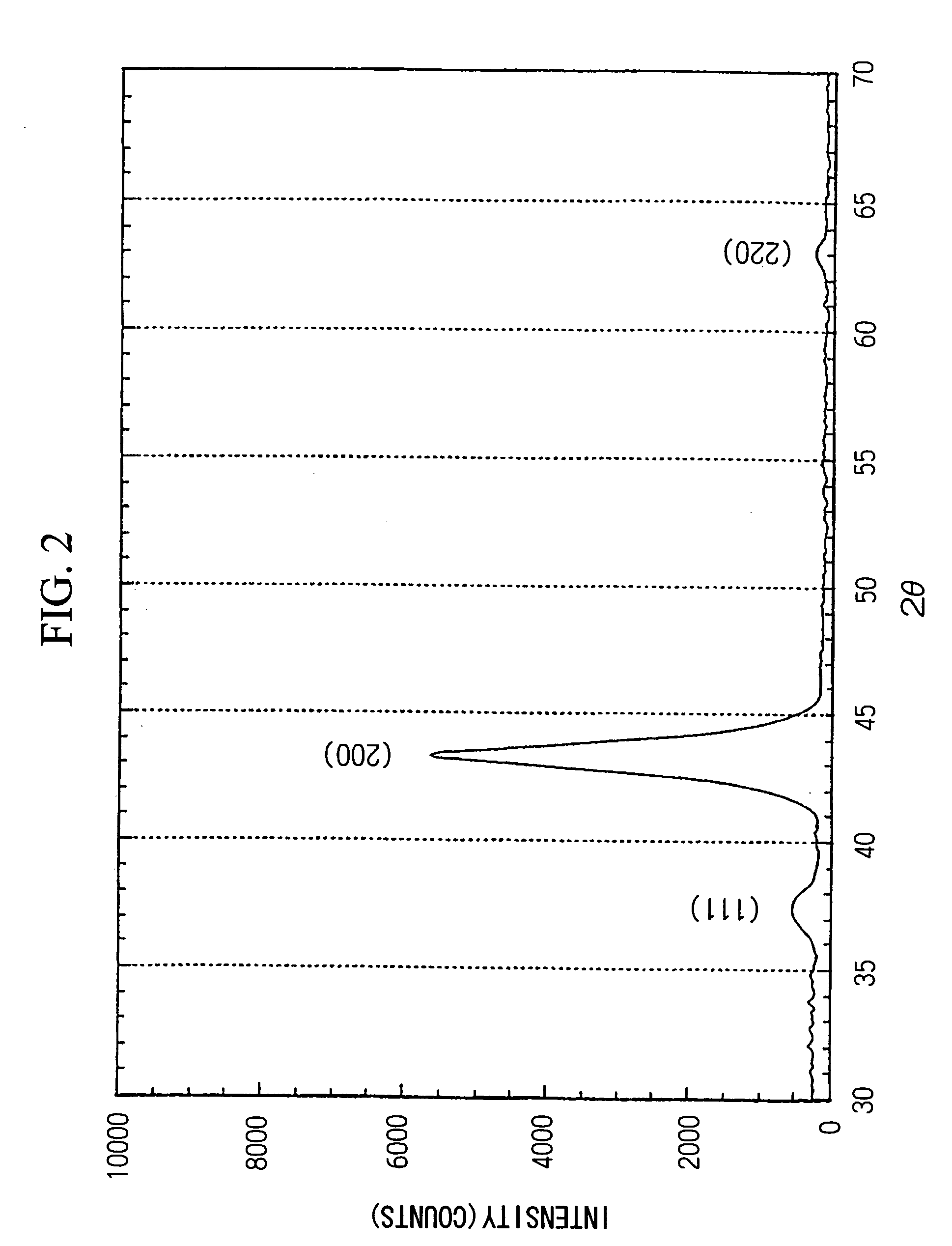
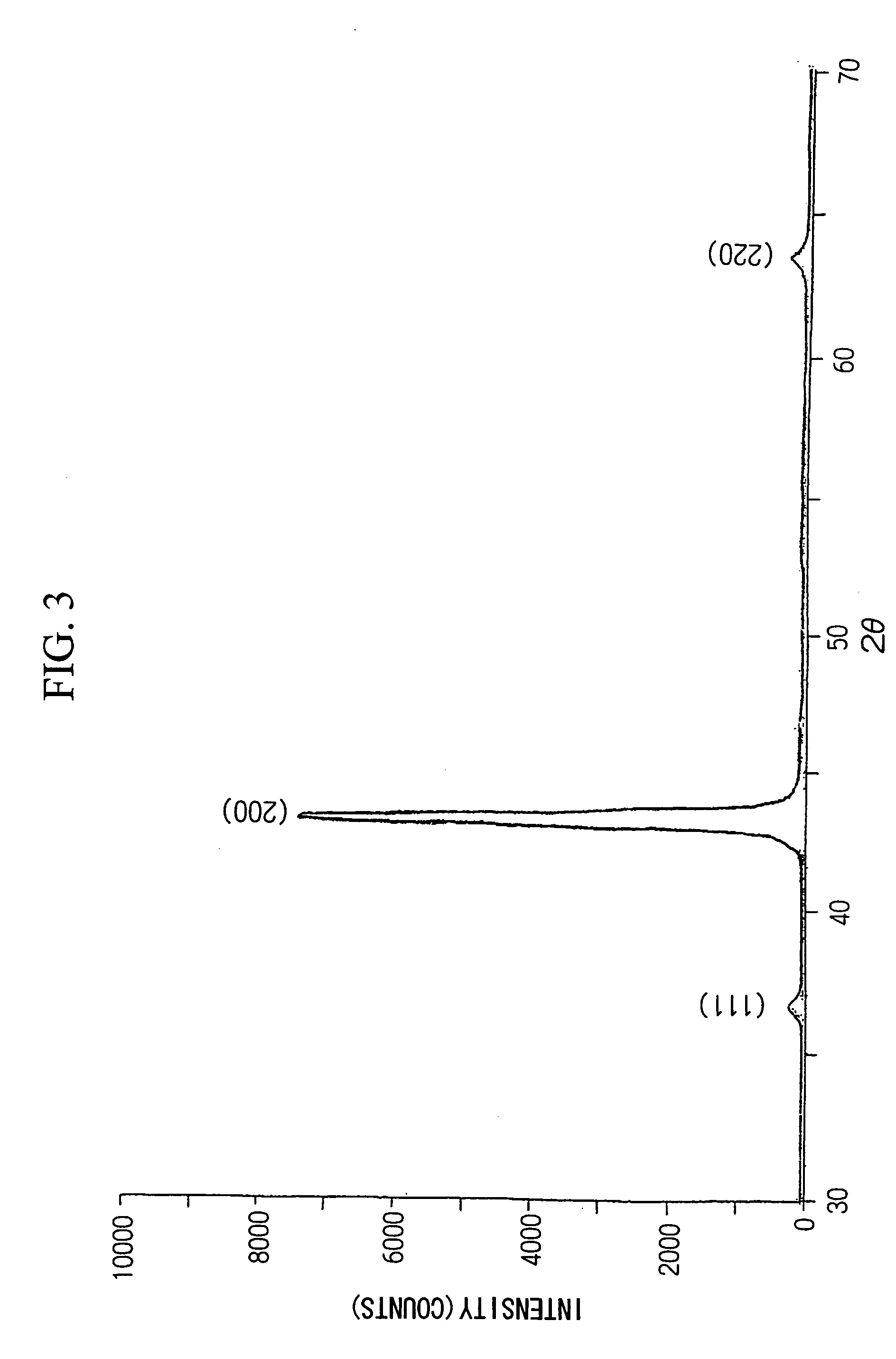
| 2θ | aaaaa | aaaaa |
Abstract
Description
Claims
Application Information