Actuator provided with grounding terminal

a technology of grounding terminal and actuator, which is applied in the direction of supporting/enclosing/casing, dynamo-electric machines, structural associations, etc., can solve the problems of deteriorating workability, failure to conduct static electricity and electromagnetic noise, and electrostatic damage of electronic parts, so as to prevent electrostatic damage

Active Publication Date: 2006-12-19
MINEBEAMITSUMI INC
View PDF16 Cites 37 Cited by
  • Summary
  • Abstract
  • Description
  • Claims
  • Application Information

AI Technical Summary

Benefits of technology

[0020]An object of an illustrative, non-limiting embodiment of the present invention is to overcome the disadvantage described above, and to provide an actuator which is prevented from getting electrostatically charged and having effects of noises. Also, the present invention is not required to overcome the disadvantage described above, and an illustrative, non-limiting embodiment of the present invention may overcome a different disadvantage or may not overcome any disadvantages.
[0022]In the aspect of the present invention, the grounding terminal may be an electrically conductive and elastic plate, and may comprise: a flat portion; a curved portion continuous from one end of the flat portion, and adapted to make contact with the one stator yoke located closer to the housing; an extension portion perpendicularly continuous from the other end of the flat portion; and positioning portions perpendicularly continuous from respective both sides of the flat portion (that is, the positioning portions comprises a first positioning portion and a second positioning portion, wherein the first positioning portion is perpendicularly continuous from one side of the flat portion, and the second positioning portion is perpendicularly continuous from the other side of the flat portion), and the extension portion and the positioning portions, together with a part of the flat portion (i.e., the flat portion among the extension portion and the positioning portions), may snap-fittingly receive the printed board such that the extension portion makes connection to the land portion of the printed board. Accordingly, the grounding terminal and the printed board can be connected to each other firmly and easily, and soldering work at the land portion can be easily done.
[0025]In the aspect of the present invention, the grounding terminal may be an electrically conductive and elastic plate, and may comprise: at least two flat portions; at least one upright portion each bridging two adjacent flat portions of the at least two flat portions; a curved portion continuous from an end of one flat portion (a first flat portion) of the at least two flat portions, and adapted to make contact with the one stator yoke located closer to the housing; and an extension portion perpendicularly continuous from an end of another flat portion (a second flat portion) of the at least two flat portions, and the extension portion and one upright portion of the at least one upright portion located closer to the extension portion, together with the another flat portion, may snap-fittingly receive the printed board such that the extension portion makes connection to the land portion of the printed board. Accordingly, the grounding terminal and the printed board can be connected to each other firmly and easily, and soldering work at the land portion can be easily done.
[0026]In the aspect of the present invention, the grounding wire connected to the land portion of the printed board and signal lines may be twisted together. With this simple structure, the signal lines are effectively shielded thereby preventing pickup of noises.

Problems solved by technology

An actuator using an engineering plastic as described above is apt to be electrostatically charged, and electronic parts may possibly suffer electrostatic destruction.
Also, importance is being put on electromagnetic environment in equipments and systems, and noise issues, such as EMC and EMI must be carefully considered.
The engineering plastic is light and strong but not electrically conductive therefore failing to conduct static electricity and electromagnetic noise generated in the actuator into the chassis.
The above solutions, however, have the following problems.
Also, a screwing-up process is required thus deteriorating workability.
H06-028448, the welding and crimping works result in deteriorated workability.

Method used


Image

  • Actuator provided with grounding terminal
  • Actuator provided with grounding terminal
  • Actuator provided with grounding terminal

Examples


Embodiment Construction

[0035]An exemplary embodiment of the present invention will hereinafter be described with reference to the accompanying drawings.

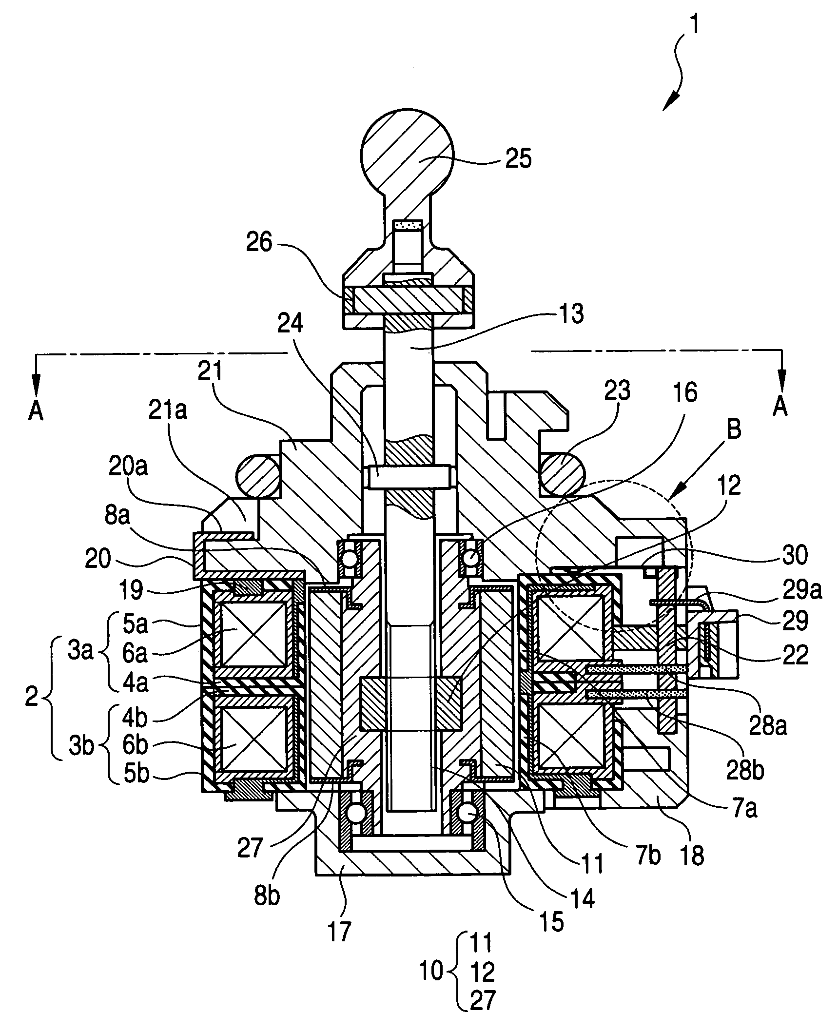
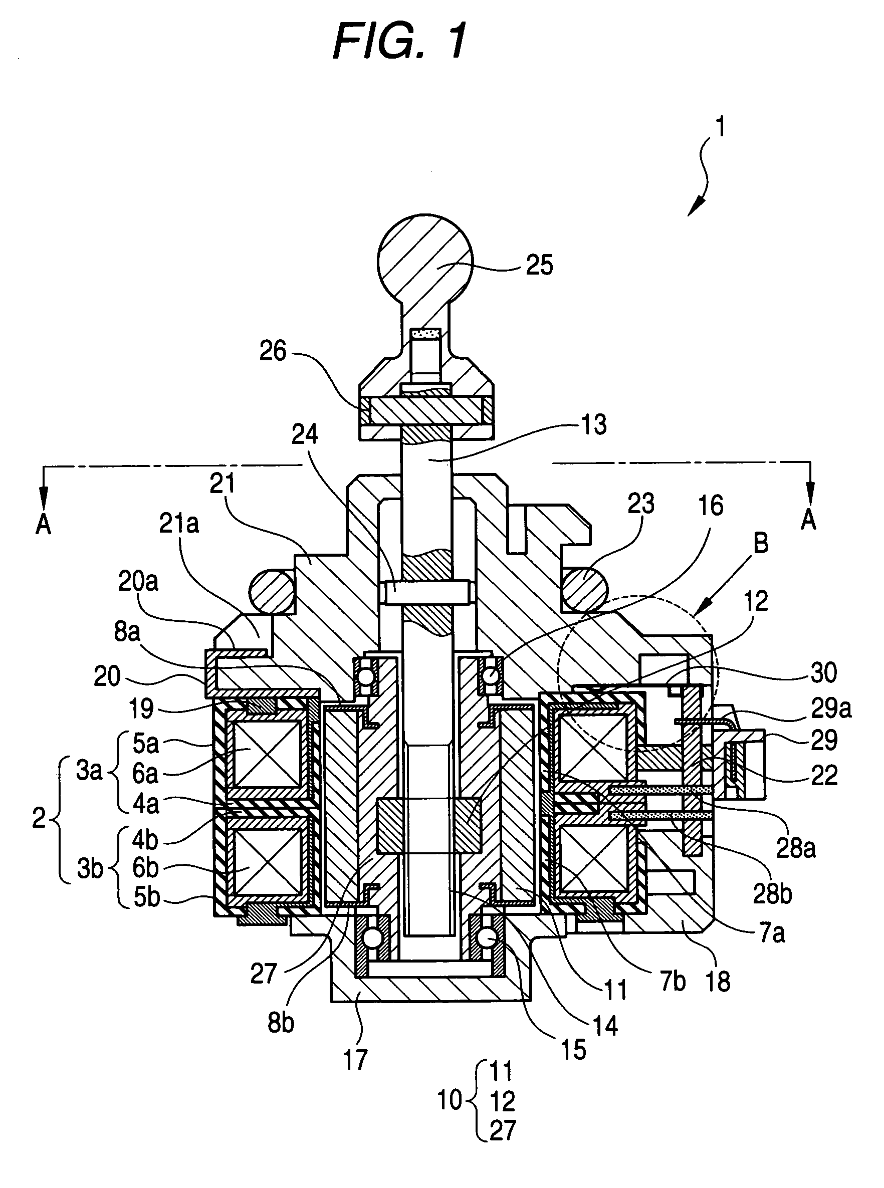
[0036]Referring to FIG. 1, an actuator 1 according to an exemplary embodiment of the present invention, which is a PM motor type actuator using a PM stepping motor, generally comprises a stator assembly 2, a rotor unit 10, an output shaft 13, and a housing 21.

[0037]The stator assembly 2 is generally structured such that a first stator unit 3a is stacked on a second stator unit 3b, and the first and second stator units 3a and 3b thus combined are fixed together by resin injection molding.

[0038]The first stator unit 3a includes inner and outer stator yokes 4a and 5a each having a plurality of pole teeth 7a, 7a, and a coil 6a disposed between the inner and outer stator yokes 4a and 5a. The second stator unit 3b includes inner and outer stator yokes 4b and 5b each having a plurality of pole teeth 7b, and a coil 6b disposed between the inner and outer stator yo...


PUM


Abstract

There is provided an actuator which includes: a stator assembly including a pair of stator yokes, and a coil disposed between the pair of stator yokes; a rotor unit including a magnet at its outer circumference and disposed inside the stator assembly; an output shaft disposed inside the rotor unit; a housing; a front plate disposed between the stator assembly and the housing; a printed board having a land portion leading to a grounding wire; and a grounding terminal having electrical conductivity and elasticity and disposed between the stator assembly and the housing. One end portion of the grounding terminal makes contact with one of the pair of stator yokes, and the other end portion thereof makes connection to the land portion of the printed board, whereby static electricity and electromagnetic noises generated in the stator assembly are conducted to the grounding wire.

Description

BACKGROUND OF THE INVENTION[0001]1. Field of the Invention[0002]The present invention relates to an actuator, and more particularly to an actuator which is free from electrostatic charge and from effects of external noises.[0003]2. Description of the Related Art[0004]Stepping motors are conveniently and well controllable and are used in various audio visual and office automation equipments. Especially, a permanent magnet (PM) stepping motor is low in cost, and therefore, recently, part of the PM stepping motor is utilized to structure an actuator, in which the rotary motion of a rotor is converted into the linear motion of an output shaft (hereinafter such an actuator is referred to as a “PM motor type actuator”). In the PM motor type actuator, a rotary-to-linear motion mechanism, which is not found in a motor structure, is provided between an output shaft (corresponding to a rotary shaft of a motor) and a mold resin portion as a sleeve having a magnet fixed thereon, whereby the rot...

Claims


Application Information

Patent Timeline
Patent Type & Authority Patents(United States)
IPC IPC(8): H02K5/00H02K5/22H02K11/00H02K37/00H02K37/14
CPCH02K5/225H02K11/0005H02K11/0089H02K11/40
Inventor SUZUKI, YUZURUHARADA, NAOYUKIMURAMATSU, KAZUO
Owner MINEBEAMITSUMI INC
Why Eureka
Try Eureka