Variable reluctance generator

a generator and variable technology, applied in the field of reluctance machines, can solve the problems that switches represent a significant portion of the cost of converters, and achieve the effect of improving the efficiency of operation

Inactive Publication Date: 2006-12-19
NIDEC SR DRIVES
View PDF54 Cites 29 Cited by
  • Summary
  • Abstract
  • Description
  • Claims
  • Application Information

AI Technical Summary

Benefits of technology

[0013]Embodiments of the invention have clear advantages in that they avoid the need to provide power switches in the way a conventional switched reluctance generator would require. The conventional power switches in a switched reluctance generator need not be present according to embodiments of the present invention. Alternatively, the mode of operation in accordance with embodiments of the present invention optionally is set up in a conventional switched reluctance drive system and used temporarily as one of a range of operating modes. For example, the drive for an electric vehicle or hybrid electric vehicle may include a switched reluctance drive as the, or part of the, prime mover. In such systems, the switched reluctance drive has been used both as a source of motive power and as a generator at appropriate times. Embodiments of the present invention allow the same drive to be used with the power switches simply rendered inactive, rather than not being present. This can lead to improved efficiency of operation.

Problems solved by technology

Though there are many topologies used for power converters for switched reluctance machines, all of them use a certain number of active switches, and these switches represent a significant portion of the cost of the converter.

Method used


Image

  • Variable reluctance generator
  • Variable reluctance generator
  • Variable reluctance generator

Examples


Embodiment Construction

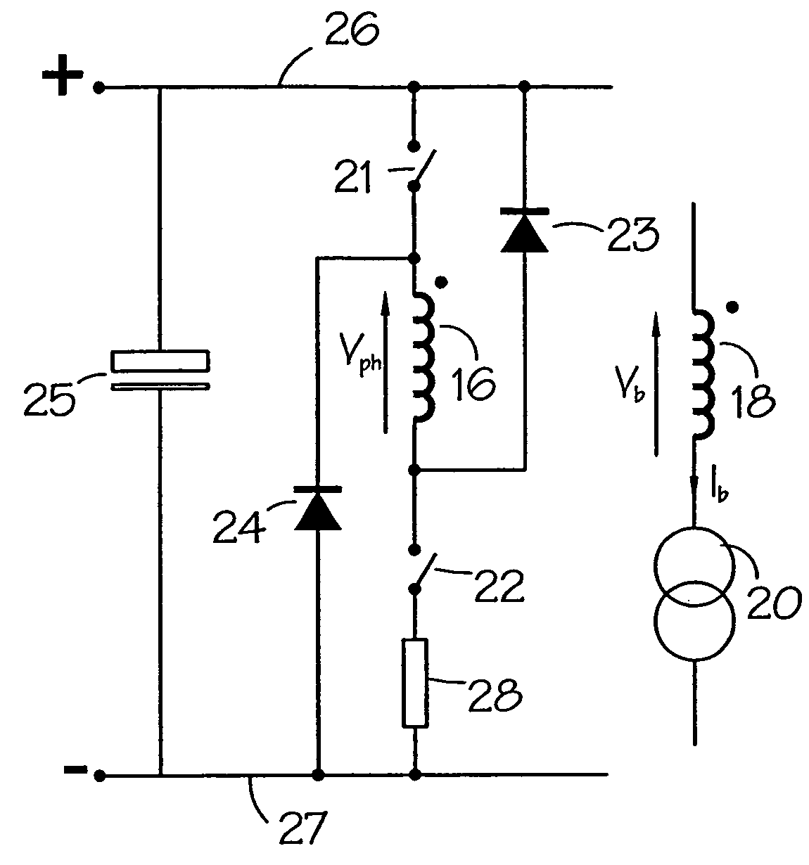
[0038]FIG. 5 is a schematic diagram of one phase of a variable reluctance machine system according to one embodiment of the invention. The system may have only one phase or it may be polyphase. The components which are the same as in the prior art system of FIG. 2 are given the same numerals. In addition, the machine has a bias winding 18 fed by a constant current source 20. The magnetic polarity of the bias winding 18 with respect to the phase winding 16 is denoted by dots. The current in the bias winding is Ib, and the voltage, Vb, induced in it by the phase voltage, Vph, by virtue of its magnetic coupling, is given by

Vb=Vph·Nb / Nph  (1)

Where Nb is the number of turns in the bias winding 18 and

[0039]Nph is the number of turns in the phase winding 16.

[0040]In physical terms, the bias winding may comprise a single winding spanning half an electrical pitch of the machine, as shown schematically in FIG. 6(a) for the example of a machine having six stator poles 61 and four rotor poles 6...


PUM


Abstract

A variable reluctance generator has phase windings and a bias winding. By controlling the excitation produced by the bias winding, the speed of the machine or the DC link, a power converter using only diodes can supply power to a DC bus. A method of operating a variable reluctance machine as a generator, the machine having at least one phase winding, includes creating a bias flux linking the or at least one phase winding, and limiting the phase voltage to a magnitude below that otherwise induced in the phase winding by the bias flux.

Description

CROSS-REFERENCE TO RELATED APPLICATION[0001]The subject matter of this application is related to the subject matter of British Patent Application No. GB 0301833.0, filed Jan. 27, 2003, priority to which is claimed under 35 U.S.C. § 119 and which is incorporated herein by reference.BACKGROUND OF THE INVENTION[0002]1. Field of the Invention[0003]The present invention generally relates to a reluctance machine operated as a generator. More particularly, embodiments of the present invention relate to the operation of a variable reluctance generator which is able to generate into a load without the use of active switches in its phase winding circuits.[0004]2. Description of Related Art[0005]The characteristics and operation of switched reluctance systems are well known in the art and are described in, for example, “The characteristics, design and application of switched reluctance motors and drives” by Stephenson and Blake, PCIM'93, Nürnberg, 21–24 Jun. 1993, incorporated herein by refere...

Claims


Application Information

Patent Timeline
Patent Type & Authority Patents(United States)
IPC IPC(8): H02H7/06H02P11/00H02P9/00H02P9/40H02P9/30H02P25/08
CPCH02P25/08H02P9/305A45D33/02A45D34/041A45D40/261A45D44/22A45D2033/001A45D2034/002A45D2040/0006A45D2200/205
Inventor RANDALL, STEVEN PAULMARCINKIEWICZ, JOSEPH GERALD
Owner NIDEC SR DRIVES
Why Eureka
Try Eureka