Optical disc device

a technology of optical discs and optical discs, applied in the field of optical disc devices, can solve the problems of generating tracking error signals, changing the voltage vosadd of the addition signal, and changing the voltage vossub of the subtraction signal

Inactive Publication Date: 2006-12-19
TEAC CORP
View PDF5 Cites 2 Cited by
  • Summary
  • Abstract
  • Description
  • Claims
  • Application Information

AI Technical Summary

Benefits of technology

[0014]According to the foregoing description, an object of this invention is to provide an optical disc device, which does not need to change the offset voltageregardless of a change in the gain of the amplifier.
[0015]According to the object mentioned above, the invention provides an optical disc device for changing intensities of light beams illuminated on an optical disc. The optical disc device comprises the following elements. A photo detecting device divided into a plurality of photo detectors are used for detecting reflected light beams of the light beams illuminated on an optical disc. A plurality of amplifiers are used for changing gains to respectively amplify output signals of the photo detectors when data are recorded and reproduced on / from the optical disc. A calculating device is also used for calculating the output signals of the amplifiers to generate the servo signals. By adding correction offset signals for correcting offset voltages of the amplifiers and the photo detectors to the amplifiers, the correction offset signals are amplified and therefore it is not necessary to change the correction offset voltages even though the gain of the amplifier is changed.
[0016]The calculating device further comprises a first calculating device and a second calculating device for respectively performing different operations on the output signals of the amplifiers. Because the correction offset signals respectively added to the amplifiers farther comprise a first correction offset value that eliminates the offset voltages from a result of the first calculating device, and a second correction offset value that eliminates the offset voltages calculated from the second calculating device, the offset voltages calculated from the first and the second calculating devices can be eliminated.
[0017]The correction offset signals respectively added to the amplifiers are signals separated from the first and the second correction offset values. Because the second is offset value calculated from the first calculating device is “0” and the first offset value calculated from the second calculating device is “0”, the offset voltages calculated from the first calculating devices can be eliminated without using the unnecessary second correction offset value and the offset voltages calculated from the second calculating devices can also be eliminated without using the unnecessary first correction offset value.

Problems solved by technology

Therefore, when data is reproduced, the incident light beams, which have the read power, are reflected by the optical disc and the reflected light beams are detected by the photo detectors and according to the detected signal, a tracking error signal is generated.
However, due to the presence of the gain G of the amplifier in the above equation, there is a problem that the correction offset voltage Vosadd of the addition signal has to be changed with the gain G of the amplifier.
However, due to the presence of the gain G of the amplifier in the above equation, there is a problem that the correction offset voltage Vossub of the subtraction signal has to be changed with the gain G of the amplifier.

Method used


Image

  • Optical disc device
  • Optical disc device
  • Optical disc device

Examples


Embodiment Construction

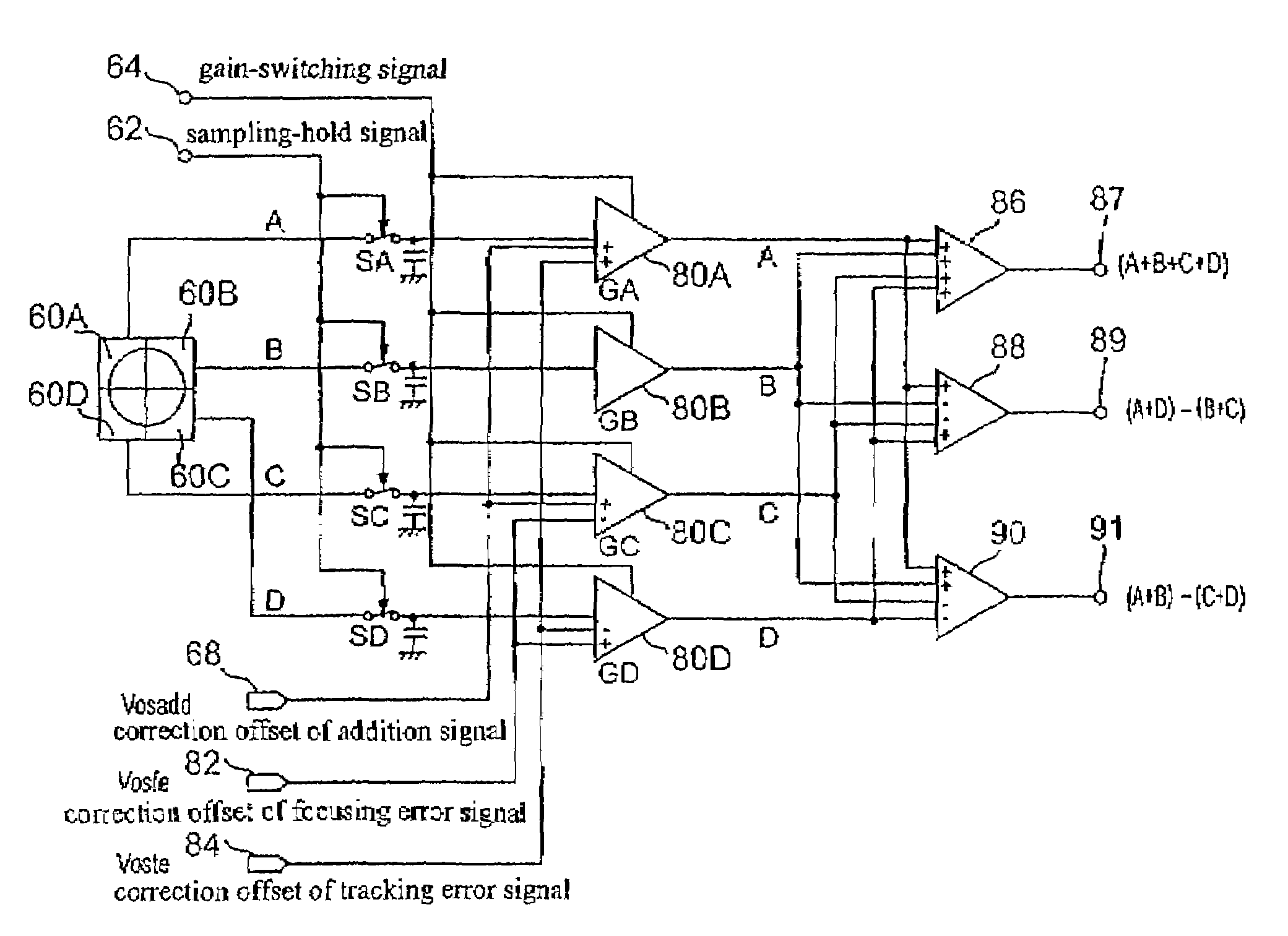
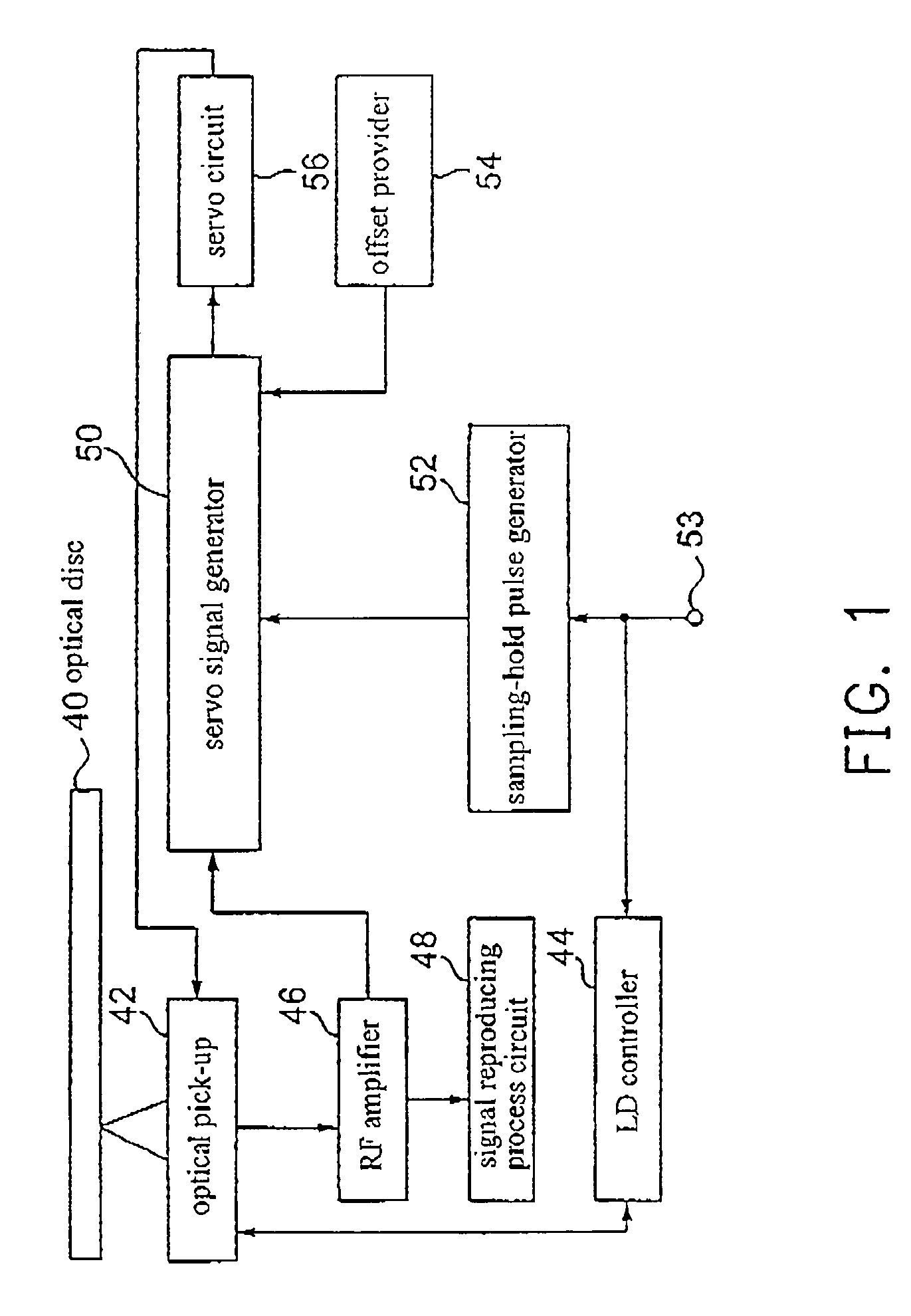
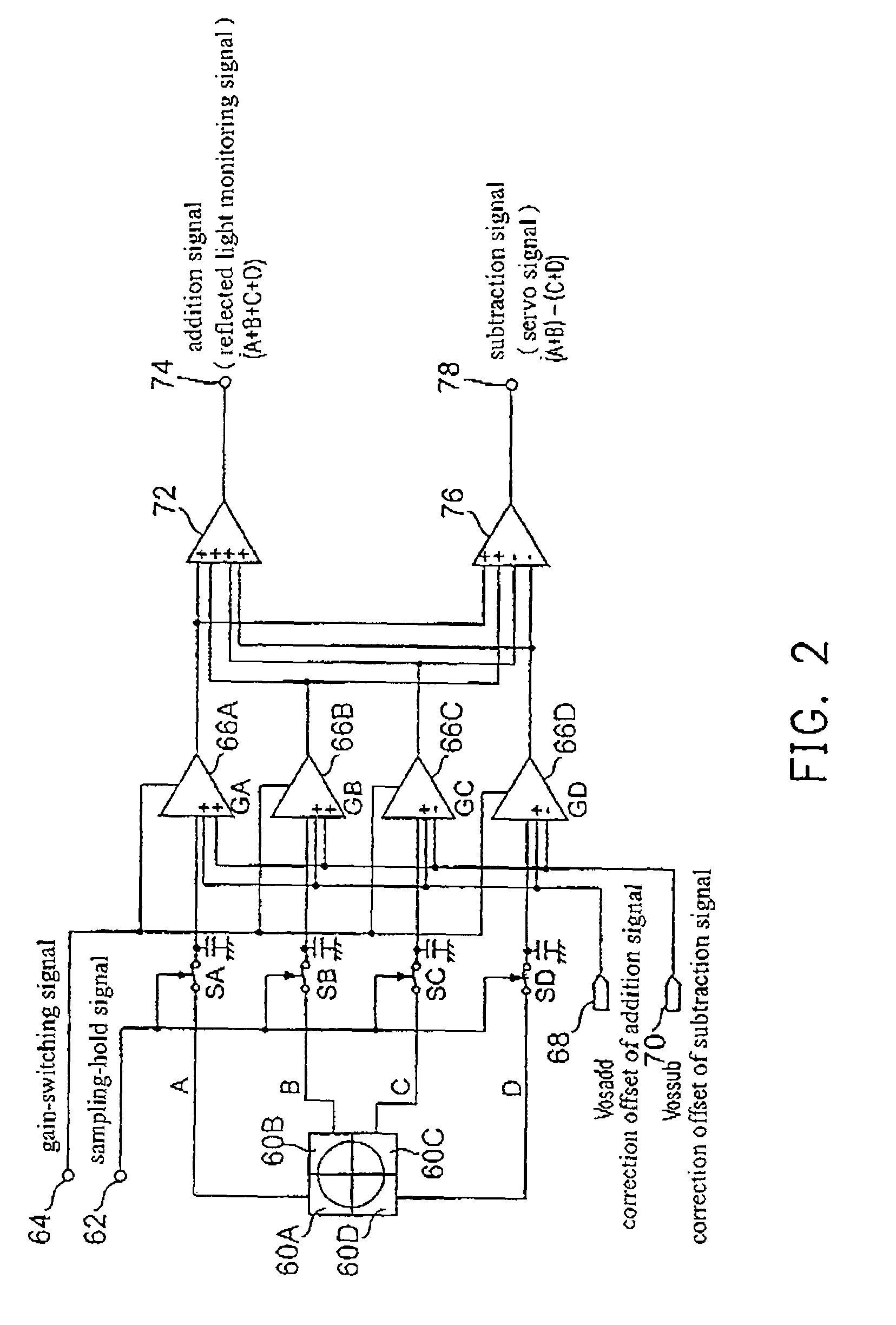
[0029]FIG. 1 is a block diagram of an optical disc device according to one preferred embodiment of the invention. A recordable disc 40, such as a CD-R or CD-RW type disc, is rotationally driven with a preset rotational speed by a spindle motor (not shown). An optical pick-up 42 is driven to move along the radial direction of the recordable disc 40 by a sled motor (not shown). The optical pick-up 42, in general, comprises an objective lens, an actuator, a ¼ wave plate, a collimator lens, a beam splitter, a light source (such as a laser diode), a front monitor and photo detectors, etc.

[0030]A laser diode (LD) controller 44 is used for controlling the laser diode in the optical pick-up 42 to emit laser beams with a read power Pb when reproducing data, or with an erase power Pe, a write power Pw and a read power Pb according to recording pulses when data is recorded. Additionally, the LD controller 44 is capable of controlling a laser driver to output laser beams with an optimal power a...


PUM

PropertyMeasurementUnit
frequencyaaaaaaaaaa
offset voltagesaaaaaaaaaa
central frequencyaaaaaaaaaa

Abstract

An optical disc device for changing intensities of light beams illuminated on an optical disc. The optical disc device comprises the following elements. A photo detecting device divided into a plurality of photo detectors is used for detecting the reflected light beams illuminated on an optical disc. A plurality of amplifiers is used for changing gains to respectively amplify the output signals of the photo detectors when recording and reproducing on/from the optical disc. A calculating device is used for calculating the output signals of the amplifiers to generate the servo signals. By adding the correction offset signals for correcting the offset voltages of the amplifiers and the photo detectors to the amplifiers, the correction offset signals are amplified. It is, therefore, not necessary to change the correction offset voltages even though the gain of the amplifier is changed and not necessary to change the offset voltage and is independent of the gain-switching of the amplifier.

Description

CROSS-REFERENCE TO RELATED APPLICATION[0001]This application claims the priority benefit of Japanese application serial no. 2000-259569, filed Aug. 29, 2000.BACKGROUND OF THE INVENTION[0002]1. Field of the Invention[0003]The present invention relates in general to an optical disc device. More specifically, the present invention relates to an optical disc device capable of recording data on an erasable optical disc.[0004]2. Description of Related Art[0005]There are several types of recordable optical discs, such as a write-once optical disc and an erasable optical disc. The write-once optical disc such as a compact disc-recordable (CD-R) and the erasable optical disc such as a compact disc-rewritable (CD-RW) or a digital versatile disc-rewritable (DVD-RW) have pregrooves for guiding on the recording optical discs. The pregrooves are wobbled slightly along the radial direction of the optical disc with a central frequency of 22.05 KHz. The address data in recording, termed as absolute ...

Claims


Application Information

Patent Timeline
Patent Type & Authority Patents(United States)
IPC IPC(8): G11B7/00G11B7/0055G11B7/09G11B7/125G11B7/126
CPCG11B7/094G11B7/0941G11B7/0943G11B7/126G11B7/0055G11B7/0901G11B7/0908
Inventor TAKASAKA, NORIKAZUMASHIMO, AKIRA
Owner TEAC CORP
Why Eureka
Try Eureka