Engine cooling system

a technology for cooling systems and engines, applied in the direction of machines/engines, mechanical equipment, cylinders, etc., can solve the problems of increasing the amount of heat dissipation capacity that can be achieved with traditional approaches, increasing the amount of heat dissipation capacity, and system passiveness, so as to reduce the decay of pressure in the coolant system

Inactive Publication Date: 2006-12-26
VOLVO TRUCKS NORTH AMERICA
View PDF46 Cites 9 Cited by
  • Summary
  • Abstract
  • Description
  • Claims
  • Application Information

AI Technical Summary

Benefits of technology

[0011]In an alternate embodiment, a flow control valve in the form of a spring loaded non-return valve is also used. A second spring loaded non-return valve allows decompression of the expansion tank to a threshold pressure level corresponding to the spring pressure of the second valve plus the pressure in the engine air inlet system. In order to dampen decay of pressure in the coolant system, a restrictor is interposed in series with the second non-return valve.

Problems solved by technology

The development of internal combustion engines for reduced exhaust emissions has resulted in significant increases in the amount of heat dissipation into engine cooling systems.
Packaging space for larger radiator cores and high energy consumption due to increased coolant and cooling air flow limit the amount of heat dissipation capacity increase that can be accomplished with these traditional approaches.
Such systems are passive and vulnerable to leaks.
These systems typically use pressure relief and pressure control to the ambient atmosphere, that causes constant or frequent air flow through to the tank or pressure source resulting in oxidization of coolant and scavenging.
In addition, the external pressure is constantly applied, resulting in parasitic losses at the pressure source.

Method used


Image

  • Engine cooling system
  • Engine cooling system
  • Engine cooling system

Examples


Embodiment Construction

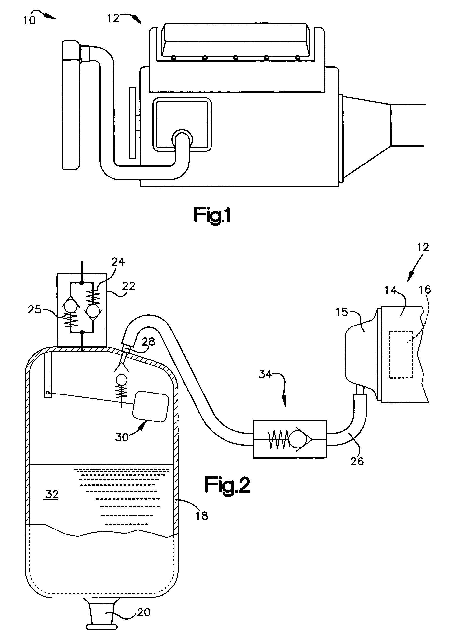
[0024]Referring to the drawings and FIG. 1 in particular, a schematic of an engine and cooling system for an over the highway truck or tractor is shown generally at 10. The truck is equipped with a turbo charged engine 12. As shown somewhat schematically in FIG. 2 the engine 12 is equipped with a cylinder head 14 having an air intake manifold 15. The engine 12 is equipped with a turbo charger pressurizing the intake manifold 15 as shown schematically at 16 in FIG. 2.

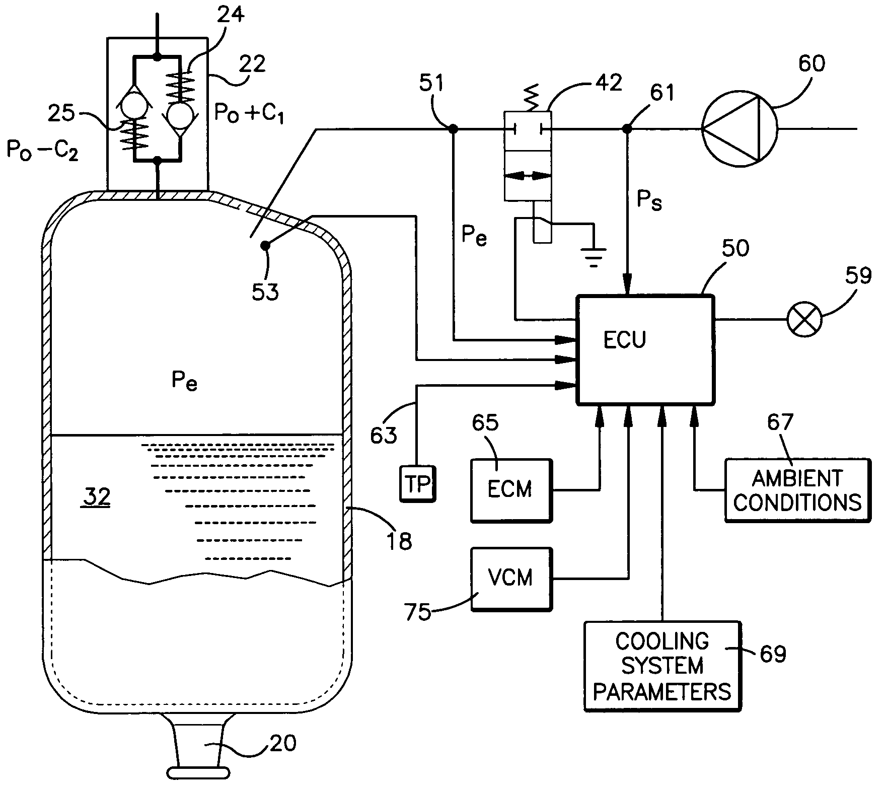
[0025]The engine 12 is equipped with a cooling system which includes an expansion tank 18, FIG. 2. The expansion tank 18 is a standard tank including an outlet 20 connected to an inlet of a water or coolant pump. The tank 18 includes a fill opening equipped with a pressure cap 22. In the disclosed embodiment, the cap 22 includes a tank pressure relief and coolant overflow valve 24 and a vacuum relief valve 25 as is now conventional in coolant systems.

[0026]A conduit 26 connects the intake manifold 15 to the expansion tan...


PUM


Abstract

An improved cooling system for a turbo charged internal combustion engine is disclosed. A conduit connects a pressurizing engine air intake to the cooling system to raise the pressure in the cooling system thereby enabling an increase of the maximum temperature which coolant in the cooling system can reach. An electronically controlled valve selectively places the expansion tank in communication with the pressurizing engine air intake to maintain a desired pressure in the tank and to prevent back flow of fluid into the engine air intake.

Description

RELATED BACK[0001]This is a Continuation-in-Part application of U.S. Ser. No. 10 / 360,156, filed on Feb. 6, 2003, which is a divisional application of U.S. Ser. No. 09 / 788,874, filed Feb. 20, 2001.TECHNICAL FIELD[0002]This invention relates to engine cooling systems and more particularly to a novel and improved cooling system in an internal combustion engine.BACKGROUND ART[0003]The development of internal combustion engines for reduced exhaust emissions has resulted in significant increases in the amount of heat dissipation into engine cooling systems.[0004]Traditionally, increases in the required amount of heat dissipation has been accomplished by improving the radiator cooling capacity through increasing the core size of the radiator. In addition, increased coolant and cooling air flow have been used to deal with the increase in required heat dissipation.[0005]Packaging space for larger radiator cores and high energy consumption due to increased coolant and cooling air flow limit t...

Claims


Application Information

Patent Timeline
Patent Type & Authority Patents(United States)
IPC IPC(8): F01P7/00F01P3/00F01P3/22
CPCF01P3/2207F01P2003/003F01P2025/04F01P2025/70
Inventor LANGERVIK, DENNIS
Owner VOLVO TRUCKS NORTH AMERICA
Why Eureka
Try Eureka