

Golf ball
a golf ball and ball technology, applied in the field of golf balls, can solve the problem of hard embedding of golf balls into grass, and achieve the effects of easy hitting of golf balls, large launch angle, and hard embedding into grass
- Summary
- Abstract
- Description
- Claims
- Application Information
AI Technical Summary
Benefits of technology
Problems solved by technology
Method used
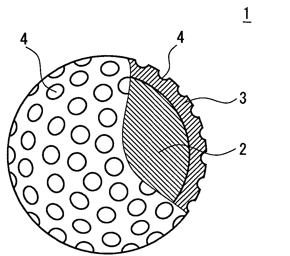
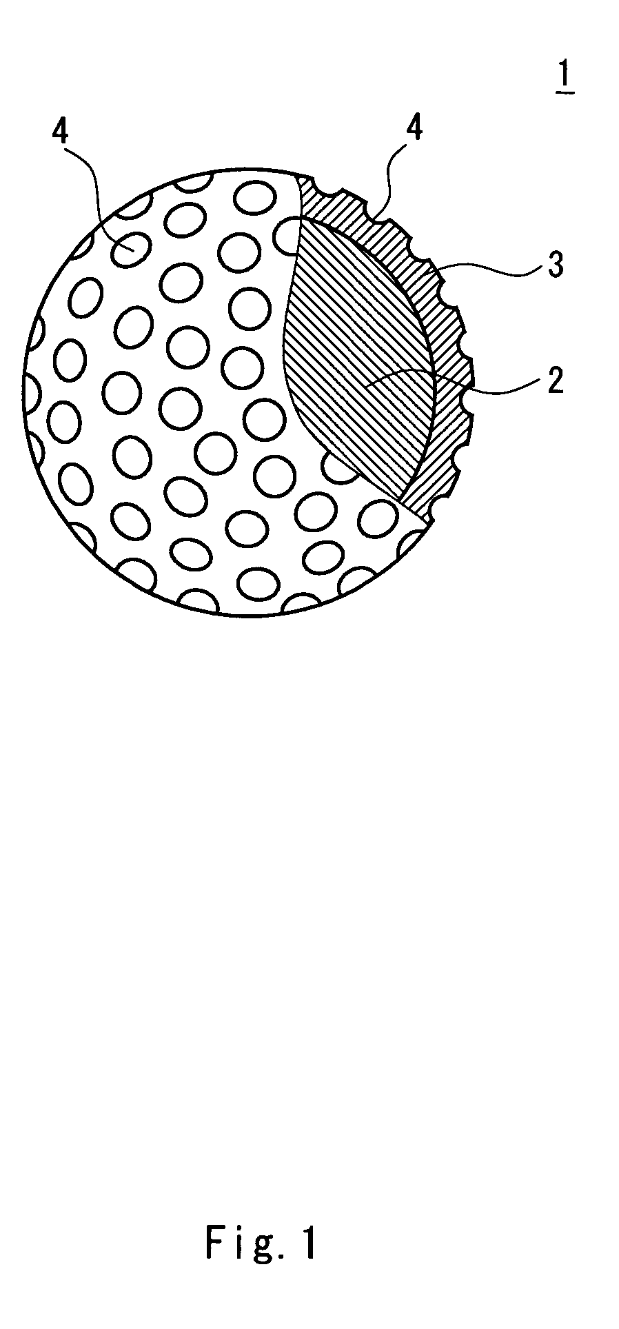
Image

Examples
example 1
[0041]A rubber composition was obtained through kneading 100 parts by weight of high cis-polybutadiene (“BR-01”, trade name by JSR Corporation), 25 parts by weight of zinc acrylate, an appropriate amount of zinc oxide, 0.8 part by weight of dicumyl peroxide and 0.5 part by weight of diphenyl disulfide. This rubber composition was placed into a mold having a spherical cavity, and kept at 160° C. for 23 minutes to obtain a core having a diameter of 38.6 mm. Next, a resin composition was obtained through kneading 50 parts by weight of an ionomer resin (the above described trade name “Himilan 1605”), 50 parts by weight of other ionomer resin (the above described trade name “Himilan 1706”), 51 parts by weight of barium sulfate and 2 parts by weight of titanium dioxide. Then, the core was placed into a mold having a spherical cavity, and thereafter the resin composition that had been melted by heating was injected around the spherical body to obtain a cover having a thickness of 2.2 mm. I...
examples 2 to 4 , example 6
Examples 2 to 4, Example 6 and Comparative Examples 1 to 3
[0042]In a similar manner to Example 1, golf balls of Examples 2 to 4, Example 6 and Comparative Examples 1 to 3 were obtained except that the constitutions were altered as shown in Table 2 and Table 3 below, and the mold was changed.
example 5
[0043]A rubber composition was obtained through kneading 100 parts by weight of high cis-polybutadiene (the above-described trade name “BR-01”), 25 parts by weight of zinc acrylate, an appropriate amount of zinc oxide, 0.6 part by weight of dicumyl peroxide and 0.5 part by weight of diphenyl disulfide. This rubber composition was placed into a mold having a spherical cavity, and kept at 160° C. for 23 minutes to obtain a core having a diameter of 37.4 mm. Next, a resin composition was obtained through kneading 100 parts by weight of a thermoplastic polyurethane elastomer (the above described trade name “Elastolan ET880”) and 40 parts by weight of tungsten powder. Then, the core was placed into a mold having a spherical cavity, and thereafter the resin composition that had been melted by heating was injected around the spherical body to obtain a mid layer having a thickness of 1.4 mm. Next, a resin composition was obtained through kneading 50 parts by weight of an ionomer resin (the ...
PUM
 Abstract
Description
Claims
Application Information