Continuous flow titration

a flow titration and continuous flow technology, applied in the field of continuous flow titration, can solve the problems of individual succession, unexpected difficulties, fluctuating end-points, etc., and achieve the effects of improving stability, high degree of experimentation, and increasing the accuracy of endpoint determination

Inactive Publication Date: 2006-12-26
AKZO NOBEL NV
View PDF6 Cites 13 Cited by
  • Summary
  • Abstract
  • Description
  • Claims
  • Application Information

AI Technical Summary

Benefits of technology

[0012]Significant changes over prior art have been demonstrated whereby the addition of a pressure drop between the point of reagent delivery and the sample in the titration channel was an unforeseen and still more important feature for other fundamental functions of the present invention, as is explained below. Experimental results demonstrate that this method results in a stable system free from flow disturbances and henceforth a significantly increased accuracy for endpoint determination.
[0013]The improved stability gained from this method has also lead to a significant improvement whereby a continuous feed-back control based on a monitoring of the end-point, automatically regulates the ratio of sample to pre-titrating reagent. The present invention allows continuous and automatic titration to be performed over a wide range of sample concentrations and conditions with a high degree of accuracy—experimental results demonstrate the ability to accurately, precisely and in real time, titrate a sample which continuously changes in concentration of up to 2.5 orders of magnitude over a 24 hour period of unattended operation.

Problems solved by technology

While gradient techniques have been shown to adapt well to on-line systems, time is still required to generate a concentration gradient which results in a succession of individual results.
Experimental work carried out to apply the principle and use of the method described by DE-A1-2001 707 lead to unexpected difficulties.
It was discovered that unless all flows (sample as well as titrant) were extremely constant, fluctuating end-points and inconsistent results were observed.
The majority of pumps, e.g. peristaltic or piston-driven pumps, produce small variations in flow rate that adversely affected the resulting accuracy of the titrations.

Method used


Image

  • Continuous flow titration
  • Continuous flow titration
  • Continuous flow titration

Examples


experiment 1

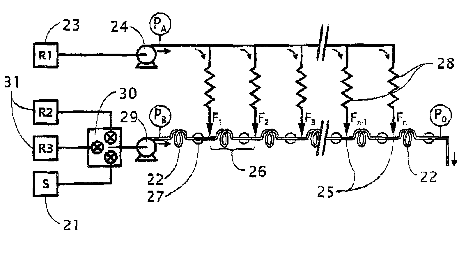
[0069]Referring to FIG. 1, the effect of varying the said pressure difference ratio measured between the titrant delivery point PA and the sample exit point P0 of the conduit with respect to the total pressure difference between the sample delivery point PB and the sample exit point P0 of the conduit is investigated.

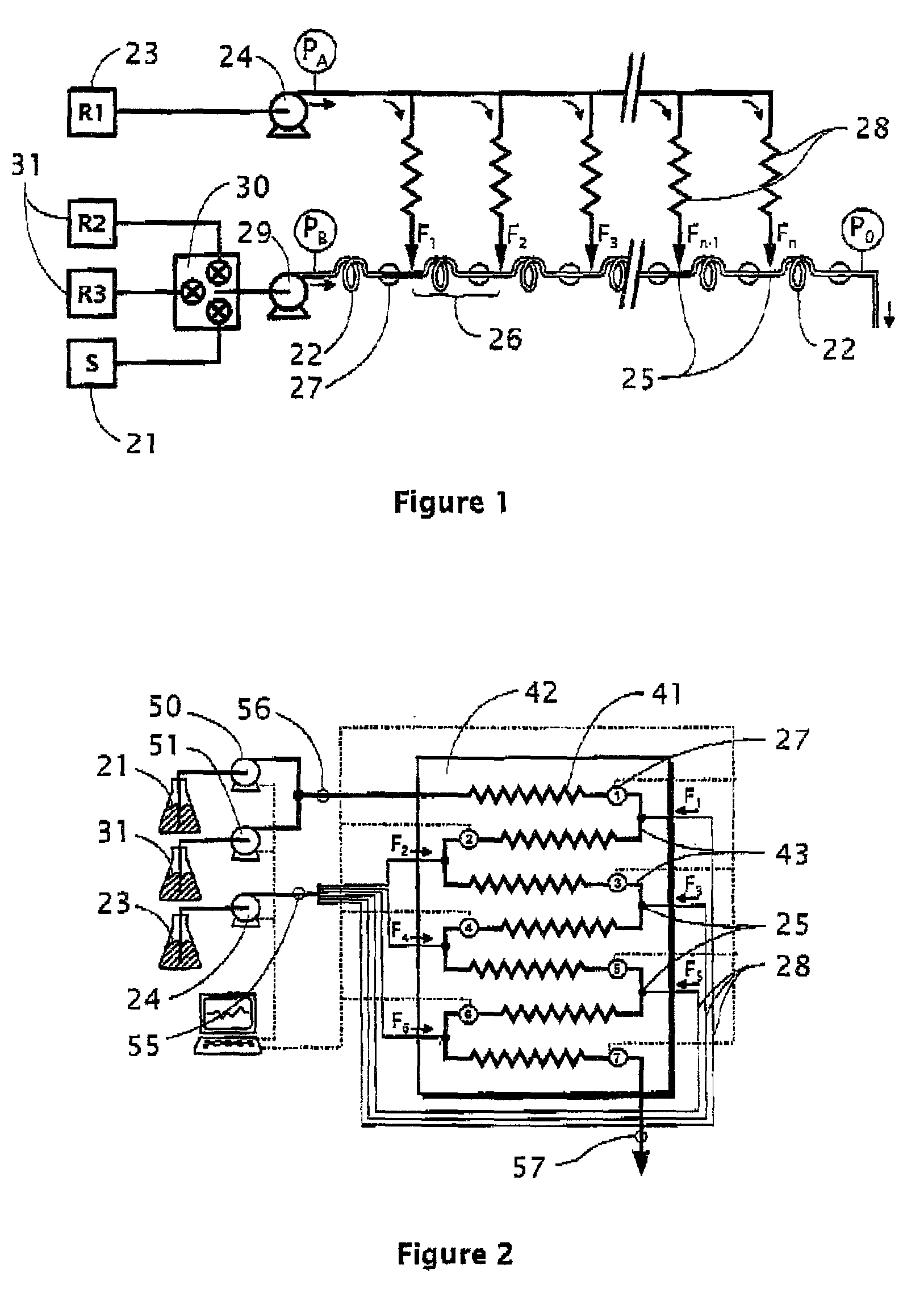
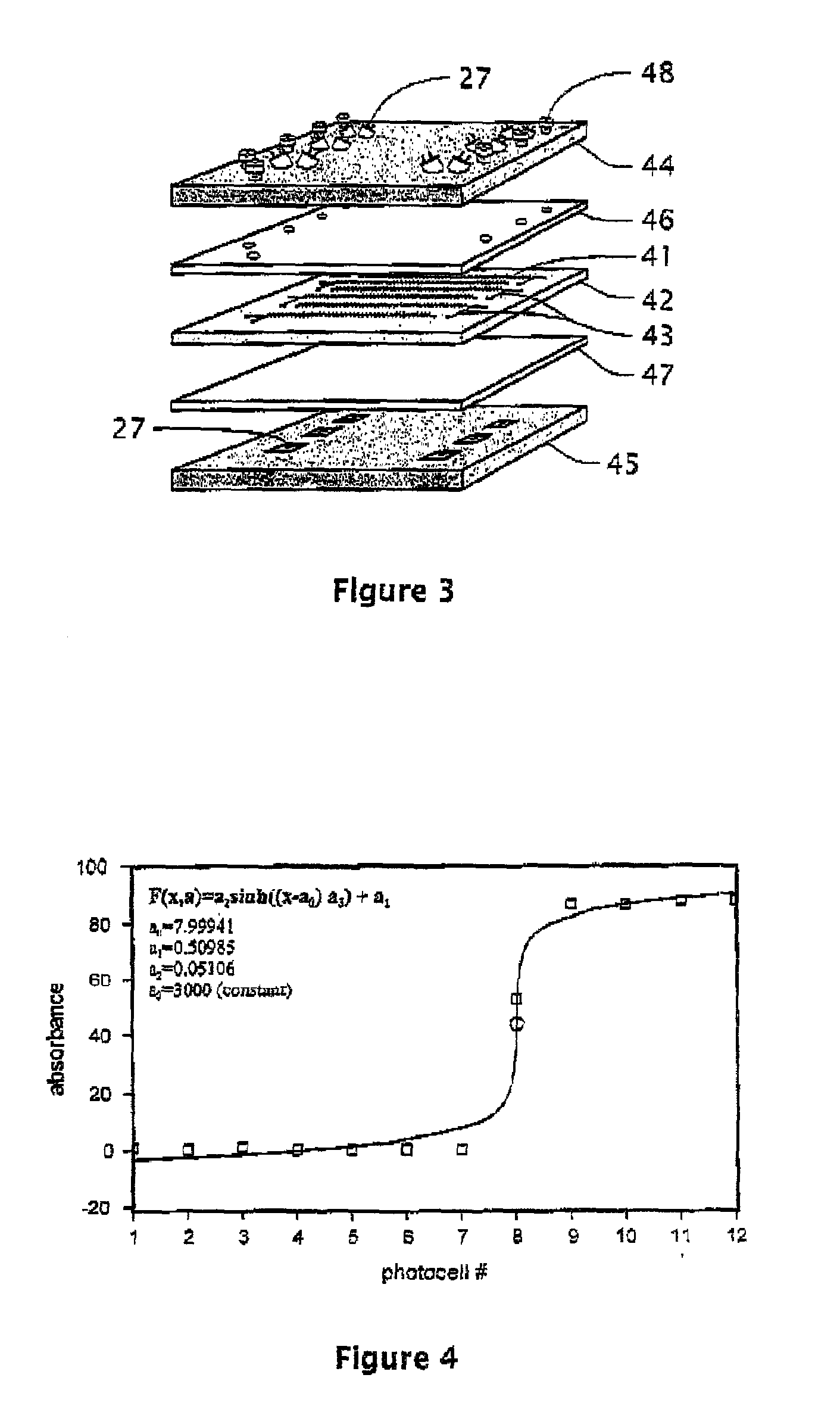
[0070]The experimental set-up is schematically depicted in FIG. 2 and a simplified representation of the actual experimental construction is given in FIG. 3. The sample conduit 22 was constructed with a zig-zag mixing channel 41 that was machined into a Plexiglass™ board 42 that ensured a thorough mixing of sample with reagent. Additional channels 43 were machined to allow both internal and external fluid transport to and from the mixing channels 41. The Plexiglass™ board 42 was sandwiched between two metal plates 44, 45 and a rubber gland 46, 47 to seal the top of the channels 41 and to mount external fluidic connectors 48 and detection devices 27. The experimental cons...

experiment 2

[0075]This experiment looks at the effect of proportioning the sample 21 and pre-titrating reagent 31, the range of the titration apparatus, accuracy and stability.

[0076]The experimental set-up is schematically depicted in FIG. 2 and described in Experiment 1, however in this experiment the apparatus utilizes a conduit comprising twelve individual sectors 26 utilizing eleven consecutive titration reagent entrance positions 25 and twelve detection devices 27. The titrating and pre-titrating reagent 23, 31 is 10 mM NaOH with 1×10⁻⁵ M Bromothymol blue indicator. The titrant flowrate was 0.25 mL.min−1, corresponding to an average flowrate of approximately 23 μL.min−1 at each consecutive titration reagent entrance position 25, and the combined flowrate of sample 21 and pre-titrating reagent 31 was 3.75 mL.min−1. The pressure difference (PA−P0) between the reagent delivery point PA and the sample exit point P0 of the conduit was approximately 70 bar and the pressure difference (PB−P0) bet...

experiment 3

[0081]This experiment looks at the implementation of a feed back controller in order to automatically control the proportioning of sample and pre-titrating reagent based on a continuous monitoring of the end-point.

[0082]The experimental set-up used in this experiment is the same as that used in experiment 2, however the control of the pre-titration is automated by the implementation of a fuzzy logic controller (FLC) based on a monitoring of the end-point, as demonstrated in FIG. 5. The titrating and pre-titrating reagent used was 0.01 M NaOH with 5×10⁻⁵ M Bromothymol blue indicator. The sample was an acetic acid solution whereby the concentration could be either kept constant or varied, either gradually or suddenly, the operator manually determining the rate and extent of the sample concentration change.

[0083]The result of the continuous titration, performed over a period of 24 hours, is given in FIG. 6. During this time interval, 49 297 consecutive titrations were logged. The stabi...


PUM


Abstract

The present invention relates to a method for titration comprising guiding a sample to be titrated through a conduit, adding a reagent to said conduit at at least two entrance positions along said conduit in such a manner that said reagent will react with the sample within at least one individual sector of the conduit, defined as the space between two consecutive entrance positions or a final individual sector defined between a final entrance position and a sample exit point of the conduit, while at least one detection device positioned at the end of each sector of said conduit register the chemical and/or physical status. A pressure difference is provided between the reagent delivery device and the sample conduit such that the pressure difference measured between the reagent delivery device and the end of the final individual sector is controlled to be greater than the total pressure drop between the sample delivery point and the end of the final individual sector. The invention further relates to an arrangement for carrying out said method.

Description

[0001]This application claims priority from U.S. Provisional Application No. 60 / 276,299, filed on Mar. 16, 2001, the subject matter of which is hereby incorporated by reference in its entirety.TECHNICAL FIELD[0002]The present invention relates, in general, to the field of volumetric analysis, and more particularly to continuous flow titration.BACKGROUND OF THE INVENTION[0003]Titration is one of the most selective and accurate analytical techniques available for the quantitative determination of soluble chemical compounds. In titrimetry, substances are quantified by measuring the volume of a solution with known concentration of reagent that is required for a defined, chemical conversion with the substance being analyzed. Generally, reagent, herein referred to as the “titrant”, is added to the sample until one can determine the point at which the sample is completely consumed by the titrant, herein referred to as the “end-point”, by means of a readily measurable change in a physical o...

Claims


Application Information

Patent Timeline
Patent Type & Authority Patents(United States)
IPC IPC(8): G01N31/16G01N37/00
CPCG01N31/166Y10T436/116664
Inventor ROERAADE, JOHANRICE, MATTHEW
Owner AKZO NOBEL NV
Why Eureka
Try Eureka