
Laser output beam wavefront splitter for bandwidth spectrum control

a laser output beam and bandwidth spectrum technology, applied in the field of light sources, can solve the problems of depth of focus, inability to work, and the lowering of laser output caused by bandwidth narrowing to a small valu

Active Publication Date: 2006-12-26
CYMER INC
View PDF67 Cites 63 Cited by
  • Summary
  • Abstract
  • Description
  • Claims
  • Application Information

AI Technical Summary

Benefits of technology

The patent describes an apparatus and method for controlling the bandwidth of a laser output light pulse beam. It uses a dispersive optic to select the center wavelength of each pulse based on the angle of incidence of the laser light pulse beam. A tuning mechanism is used to select the angle of incidence of the beam on the dispersive optic for each portion of the pulse. This results in a laser beam with multiple portions that have different center wavelengths. The technical effect is the ability to control the bandwidth of the laser output light pulse beam, which is useful in various applications such as optical communication systems.

Problems solved by technology

It is well known in the art of semiconductor manufacturing that depth of focus (“DOF”) is an important issue.
In addition, lowering of laser output caused by bandwidth narrowing can be limited to a small value because the bandwidth-narrowing device is disposed between the reflecting mirror and the output mirror.
Yan also proposes the generation of three output beams from a single laser system, but the embodiment proposed is not workable.
The image in photoresist is formed by the composite of the multiple exposure passes.Several difficulties result from this FLEX process with both step and scan as well as step and repeat exposure implementations.
Multiple pass exposure results in additional overlay (image placement) errors and image blurring.
It has also been determined that isolated and dense lines are affected in different ways, with some benefit for isolated lines but little improvement for dense lines.
However, the range of useful acousto-optical materials is limited, either because of their low figure of merit or as a consequence of the strong attenuation of ultrasound.

Method used


Image

  • Laser output beam wavefront splitter for bandwidth spectrum control
  • Laser output beam wavefront splitter for bandwidth spectrum control
  • Laser output beam wavefront splitter for bandwidth spectrum control

Examples


Embodiment Construction

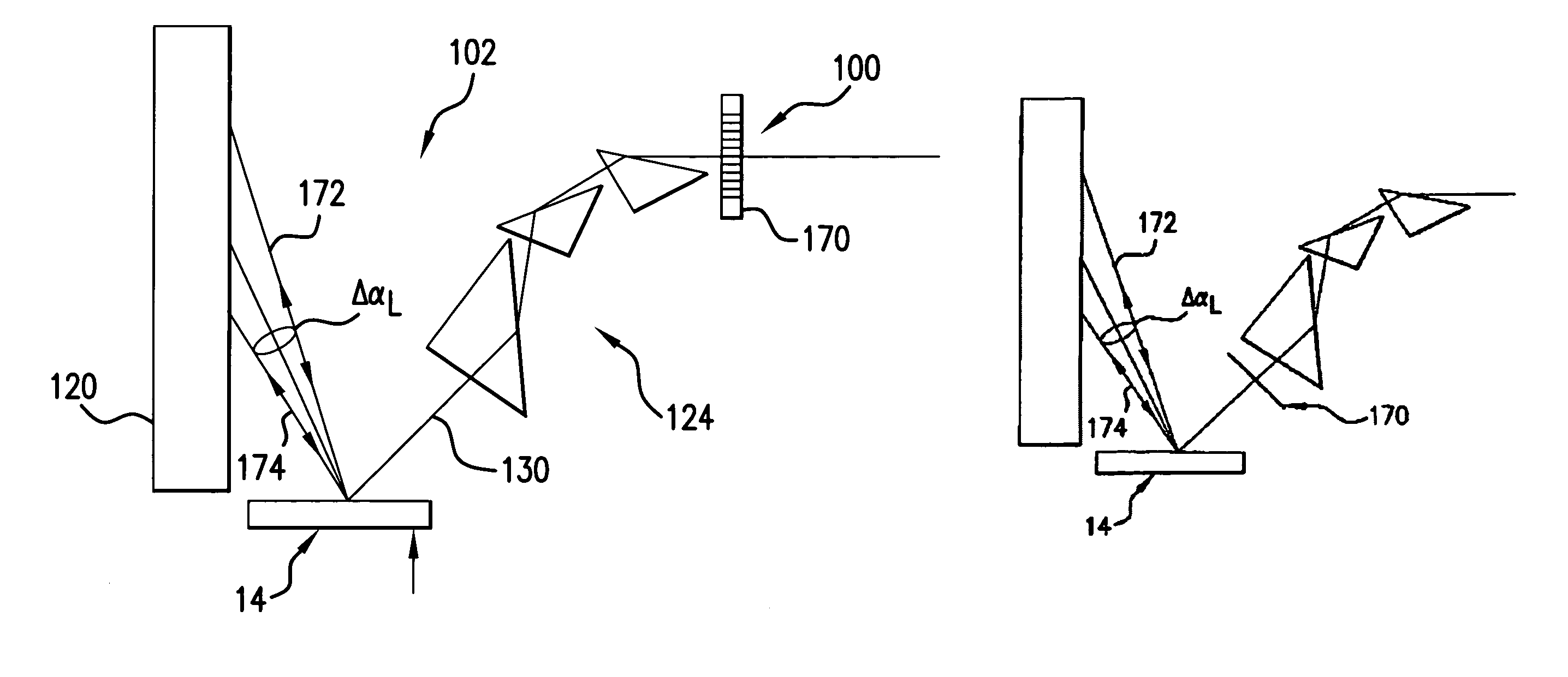
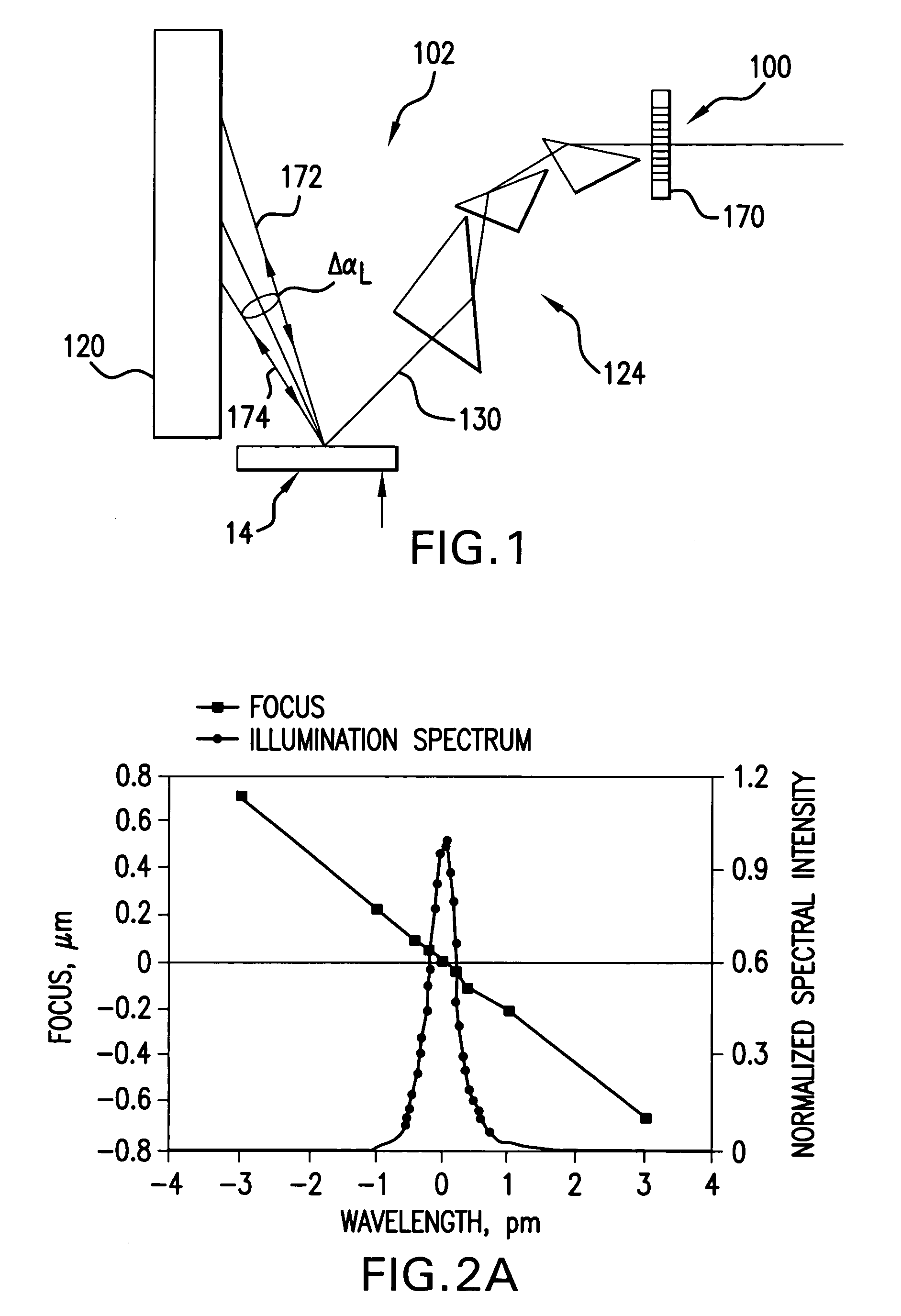
[0050]Applicants propose according to aspects of embodiments of the present invention several alternative improvements to providing a laser light source output that is an improvement to previously proposed ways of providing multiple peaked spectra, e.g., for enhancing DOF. According to aspects of an embodiment of the present invention a dithered center wavelength may be provided in which a conventional single-peak spectrum having a center wavelength has its center wavelength changed quickly, e.g., in an alternating pattern within a single scan window, i.e., from pulse to pulse to first have at least one center wavelength and then at least one other. This may be done in one aspect of an embodiment of the present invention, utilizing very agile wavelength control. Alternatively there can be provided in the same laser output lithography light source beam a plurality of pulses, each with a multiple-peaked spectrum produced in every pulse, or substantially every pulse, such that over, e....


PUM

PropertyMeasurementUnit
FWHM bandwidthaaaaaaaaaa
wavelengthaaaaaaaaaa
FWHMaaaaaaaaaa

Abstract

Apparatus / method providing bandwidth control in narrow band short pulse duration gas discharge laser output light pulse beam producing systems, producing a beam comprising pulses at selected pulse repetition races, e.g., comprising a dispersive bandwidth selection optic selecting at least one center wavelength for each pulse determined at least in part by the angle of incidence of the beam containing the respective pulse on the optic; a tuning mechanism operative to select at least one angle of incidence of the beam containing the respective pulse upon the optic; the tuning mechanism comprising a plurality of incidence angle selection elements each defining an angle of incidence for a different spatially separated but not temporally separated portion of the pulse to return from the optic a laser light pulse comprising a plurality of spatially separated but not temporally separated portions, each having one of at least two different selected center wavelengths.

Description

FIELD OF THE INVENTION[0001]The present invention relates to light sources, e.g., for integrated circuit lithography illumination sources requiring spectral engineering within a pulse or from pulse to pulse within a burst.RELATED APPLICATIONS[0002]The present application is related to Published Patent Application No. 2002 / 0167975A1, entitled LASER SPECTRAL ENGINEERING FOR LITHOGRAPHIC PROCESS, with inventors Spangler et al., published on Nov. 14, 2002, based on an application Ser. No. 10 / 036,925, filed on Dec. 21, 2001 ('925 Application”), and U.S. Pat. No. 6,671,294, issued to Kroyan et al. on Dec. 30, 2003, entitled LASER SPECTRAL ENGINEERING FOR LITHOGRAPHIC PROCESS, based on an application Ser. No. 09 / 918,773 filed on Jul. 27, 2001 (“294 patent”), the disclosures of which are hereby incorporated by reference.BACKGROUND OF THE INVENTION[0003]It is well known in the art of semiconductor manufacturing that depth of focus (“DOF”) is an important issue. Fukuda (Hitachi Central Resear...

Claims


Application Information

Patent Timeline
Patent Type & Authority Patents(United States)
IPC IPC(8): H01S3/22H01S3/223G03F7/20H01S3/08H01S3/097H01S3/10H01S3/1055H01S3/13
CPCG03F7/70025G03F7/70575H01S3/0812H01S3/097H01S3/1055H01S3/08059H01S3/1305H01S3/22
Inventor SANDSTROM, RICHARD L.BROWN, DANIEL J. W.ERSHOV, ALEXANDER I.FOMENKOV, IGOR V.PARTLO, WILLIAM N.
Owner CYMER INC
Learn More