Radiological imaging apparatus

a radiation imaging and apparatus technology, applied in the field of radiation imaging apparatus, can solve the problems of easy replacement of damaged radiation detectors, and achieve the effects of accurate image, easy replacement of damaged radiation detectors, and accurate confirmation of position

Inactive Publication Date: 2006-12-26
HITACHI LTD
View PDF17 Cites 51 Cited by
  • Summary
  • Abstract
  • Description
  • Claims
  • Application Information

AI Technical Summary

Benefits of technology

[0005]There is a demand for further improvement of diagnostic accuracy in the position and size, etc., of an affected area such as malignant tumor and there is also a demand for improvement of accuracy of images including the affected area created by a radiological imaging apparatus. It is also an important challenge to allow a damaged radiation detector to be replaced in a short time.
[0006]It is an object of the present invention to provide a radiological imaging apparatus capable of improving the accuracy of an image created and easily replacing a damaged radiation detector.
[0008]Since the other radiation detectors for detecting radiation that has passed through some radiation detectors are provided, it is possible to detect radiation emitted from the examinee by the some radiation detectors or the other radiation detectors and accurately confirm the position the radiation has reached from the some radiation detectors facing the examinee in the depth direction (position at which the radiation has been detected). Thus, it is possible to obtain an accurate image illustrating the condition of the body of the examinee. Furthermore, since the detector unit is attached to the detector support member in a detachable manner, a damaged radiation detector can be replaced easily.

Problems solved by technology

It is also an important challenge to allow a damaged radiation detector to be replaced in a short time.
Furthermore, since the detector unit is attached to the detector support member in a detachable manner, a damaged radiation detector can be replaced easily.

Method used


Image

  • Radiological imaging apparatus
  • Radiological imaging apparatus
  • Radiological imaging apparatus

Examples


embodiment 1

(Embodiment 1)

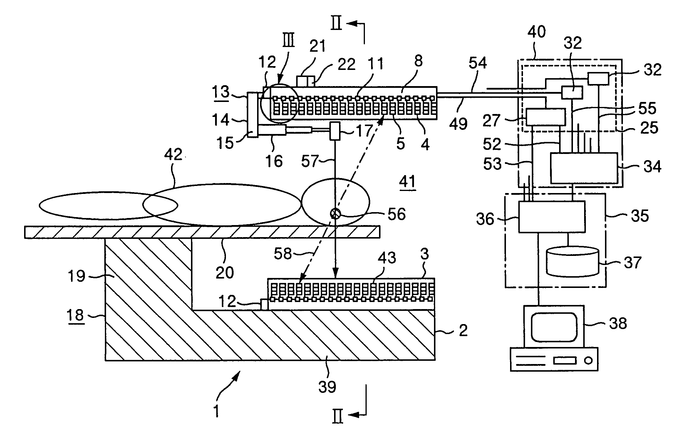
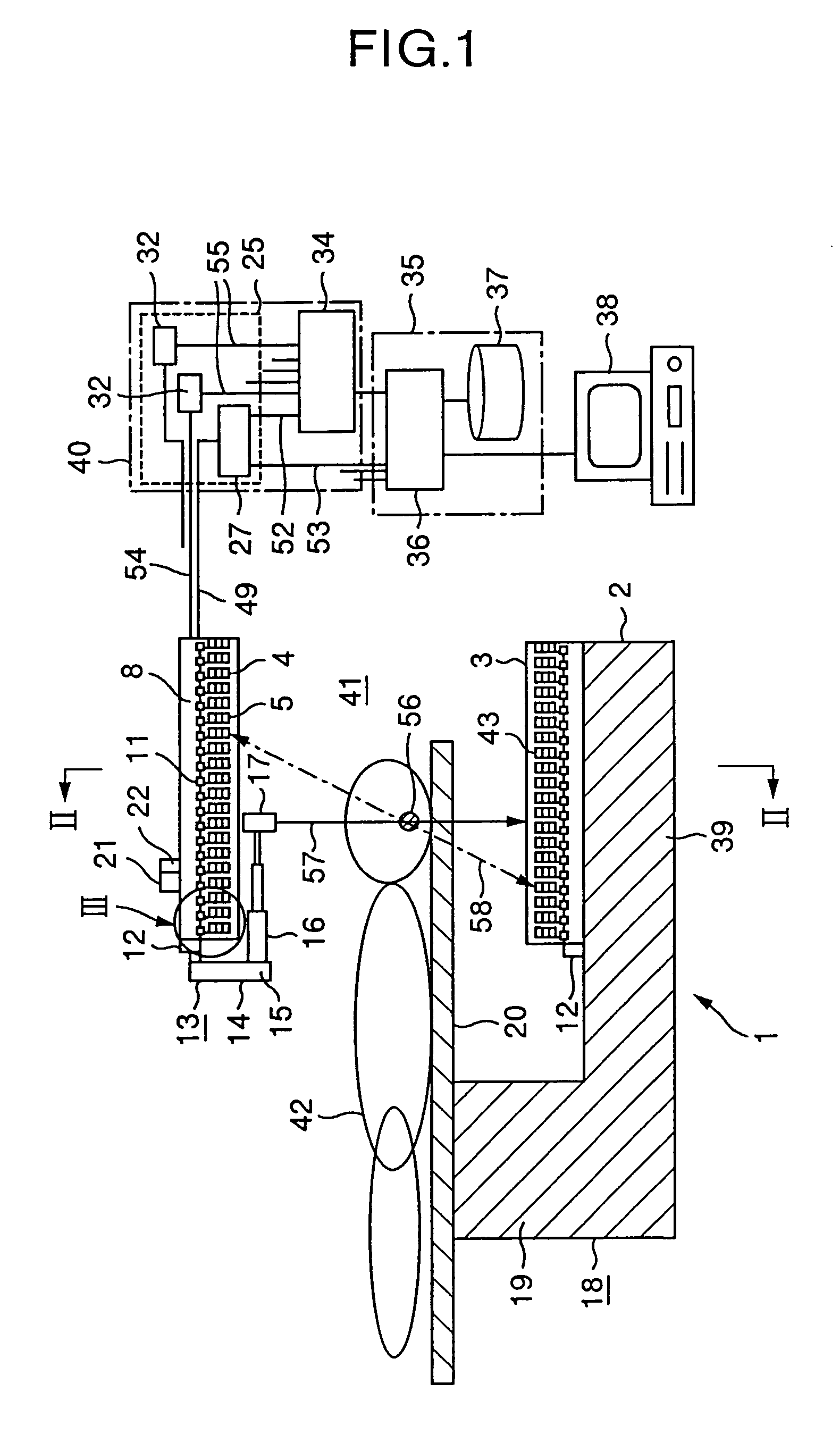
[0023]With reference now to FIG. 1 and FIG. 2, a radiological imaging apparatus which is a preferred embodiment of the present invention will be explained below. A radiological imaging apparatus 1 of this embodiment is used for a PET inspection. The radiological imaging apparatus 1 is provided with an image pickup apparatus 2, a signal processing apparatus 40, a tomographic image creation apparatus 35, an examinee holding apparatus 18, a drive apparatus control apparatus 21 and an X-ray source control apparatus 22. The examinee holding apparatus 18 includes a bed 20 on top of a bed support section 19 in such a way that the bed 20 is movable in the longitudinal direction.

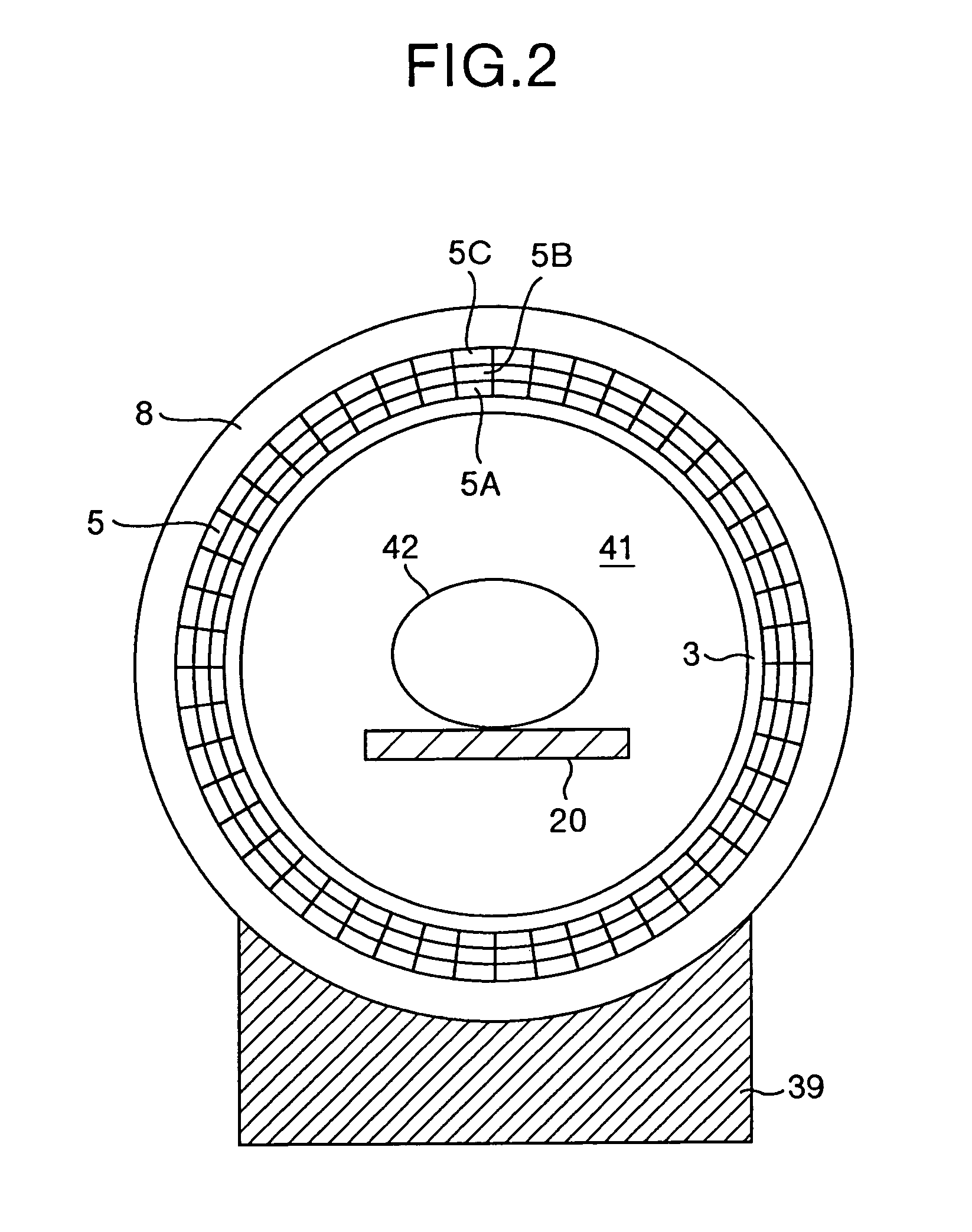
[0024]The image pickup apparatus 2 includes a casing 3, many detector units 4, a ring-shaped detector support member 8 and an X-ray source circumferential transport apparatus 13. As shown in FIG. 3 and FIG. 4, the detector support member 8 includes a ring-shaped detector support section 23 attached to a...

embodiment 2

(Embodiment 2)

[0082]A radiological imaging apparatus according to Embodiment 2 which is another preferred embodiment of the present invention will be explained below. The radiological imaging apparatus in this embodiment only differs from the configuration of the radiological imaging apparatus 1 of Embodiment 1 in the configuration of the detector unit 4. A detector unit 4A used in this embodiment having a configuration different from that of the detector unit 4 used in Embodiment 1 will be explained with reference to FIG. 10 and FIG. 11.

[0083]The detector unit 4A consists of a plurality (e.g., 9) of radiation detectors 5D arranged in 3 rows and 3 columns on one side of a support substrate 6. Each radiation detector 5D is the same semiconductor radiation detector as the radiation detector 5 and three layers of the radiation detectors 5D are arranged in the radius direction of a detector support member 8. Of one column in the radius direction of the detector support member 8, a radia...


PUM


Abstract

The image pickup apparatus of the radiological imaging apparatus of the present invention includes many detector units, a ring-shaped detector support member and an X-ray source circumferential transport apparatus. Each of the detector units is attached to the detector support section in a detachable manner. A plurality of radiation detectors provided for the detector units are arranged in three layers in the radius direction of the detector support member and in three columns in the axial direction of the detector support member. Since the radiation detectors are arranged in three layers in the radius direction, it is possible to recognize the detection position of radiation in the radius direction in detail. Furthermore, since the detector units are attached in a detachable manner, it is easy to replace damaged radiation detectors.

Description

BACKGROUND OF THE INVENTION[0001]The present invention relates to a radiological imaging apparatus, and more particularly, to a radiological imaging apparatus ideally applicable to radiological two-dimensional image pickup apparatus, X-ray computed tomography (hereinafter referred to as “X-ray CT”), positron emission computed tomography (hereinafter referred to as “PET”) and single photon emission computed tomography (hereinafter referred to as “SPECT”).[0002]Among typical radiological imaging apparatuses, which is a non-invasive imaging technology for examining functions and conformation of the body of a medical examinee, are radiological two-dimensional image pickup apparatus, X-ray CT, PET and SPECT, etc.[0003]PET inspection is an inspection consisting of administering radiopharmaceutical (hereinafter referred to as “PET radiopharmaceutical”) including positron emitters (15O, 13N, 11C, 18F, etc.) to the examinee and examining locations in the body where more PET radiopharmaceutic...

Claims


Application Information

Patent Timeline
Patent Type & Authority Patents(United States)
IPC IPC(8): A61B6/00A61B6/03G01T1/164G01T1/161G01T1/29
CPCA61B6/032A61B6/5235A61B6/037G01T1/1644G01T1/2985G01T1/1615
Inventor UENO, YUUICHIROUKITAGUCHI, HIROSHIAMEMIYA, KENSUKEUMEGAKI, KIKUOYANAGITA, NORIHITOKOJIMA, SHINICHIYOKOI, KAZUMA
Owner HITACHI LTD
Why Eureka
Try Eureka