
DDS-PLL method for frequency sweep

a frequency sweep and linear wave technology, applied in the field of analog and digital radio frequency (rf) control techniques, can solve the problems of affecting frequency accuracy and linearity, generating accurate linear wideband frequency sweeps in swept microwave spectrum analyzers, etc., and achieve the effect of accurate determination

Inactive Publication Date: 2006-12-26
TEKTRONIX INC
View PDF4 Cites 9 Cited by
  • Summary
  • Abstract
  • Description
  • Claims
  • Application Information

AI Technical Summary

Benefits of technology

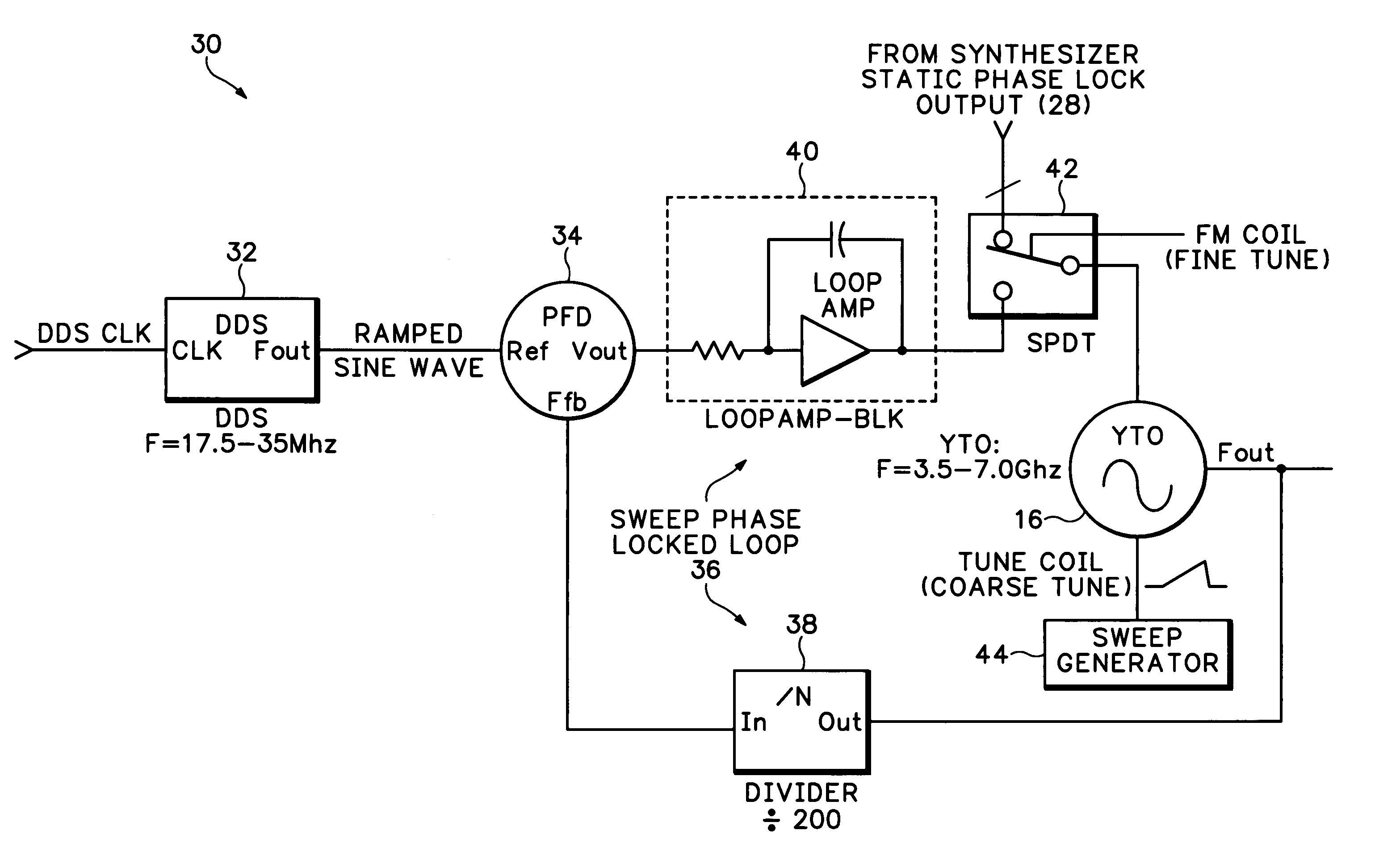
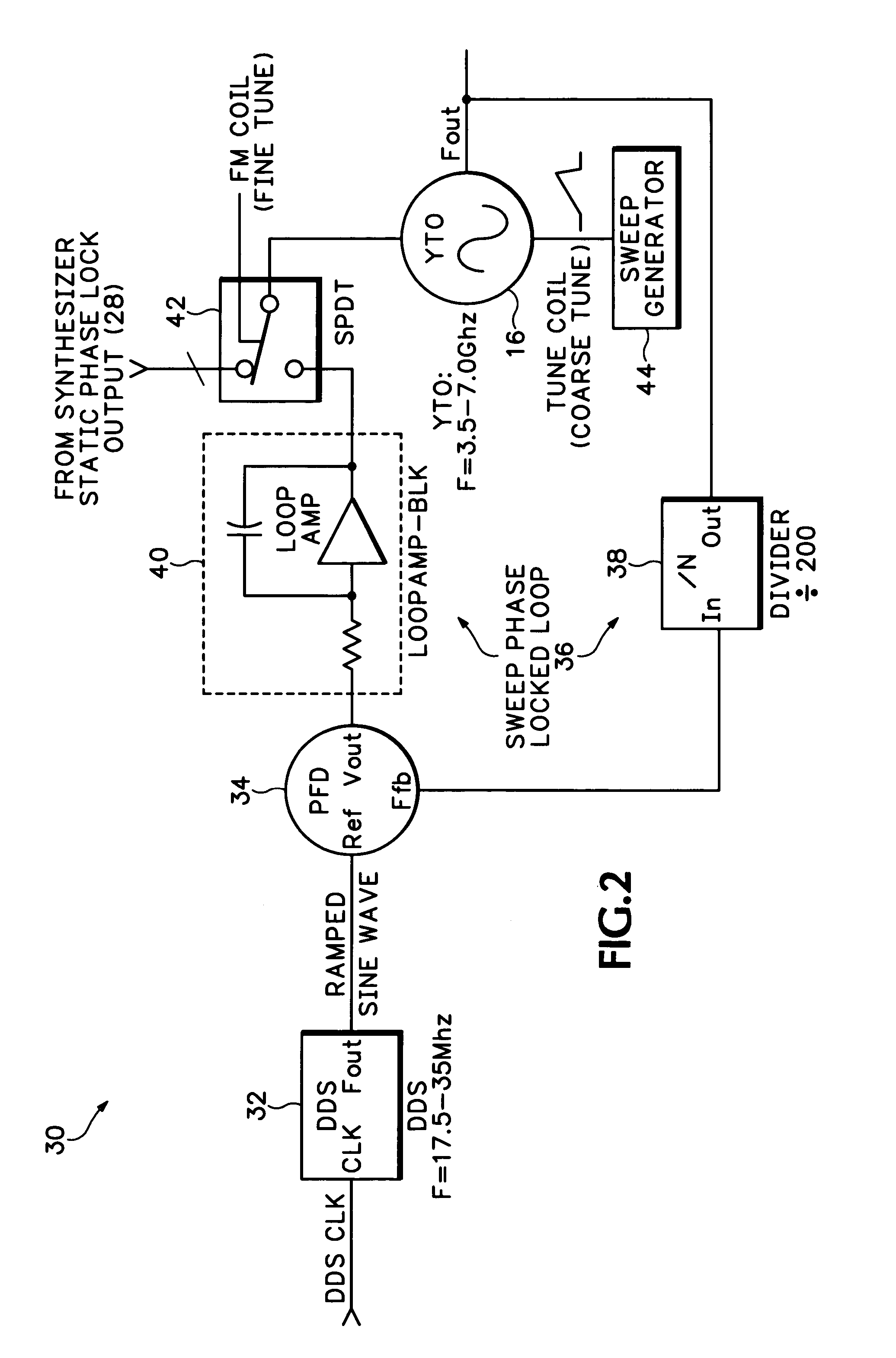
[0005]Accordingly the present invention provides a direct digital synthesizer-phase-locked loop (DDS-PLL) method for frequency sweep where the PLL controls the output frequency of a YTO and in turn is swept in frequency by a DDS whose output is applied to a frequency reference port of the PLL. A digital sweep generator provides a linear ramp signal to a coarse tuning port of the YTO, with the amplitude of the linear ramp signal determining the swept frequency span. The DDS-PLL output provides an error correction signal to a fine tuning port of the YTO to compensate for any non-linearities in the output swept frequency signal from the YTO. All parameters of the digital sweep generator may be accurately determined due to the digital architecture. The result is an accurate and linear swept frequency signal at the output of the YTO.

Problems solved by technology

Generating an accurate linear wideband frequency sweep in swept microwave spectrum analyzers has historically been hindered by a number of nuisance problems.
When these oscillators are swept over wide frequency spans, they commonly suffer from non-linearity caused by hysteresis, post-tune drift, frequency offsets, slow response time, intrinsic non-linearity and other problems which substantially hinder the frequency accuracy and linearity of these frequency sweeps.

Method used


Image

  • DDS-PLL method for frequency sweep
  • DDS-PLL method for frequency sweep
  • DDS-PLL method for frequency sweep

Examples


Embodiment Construction

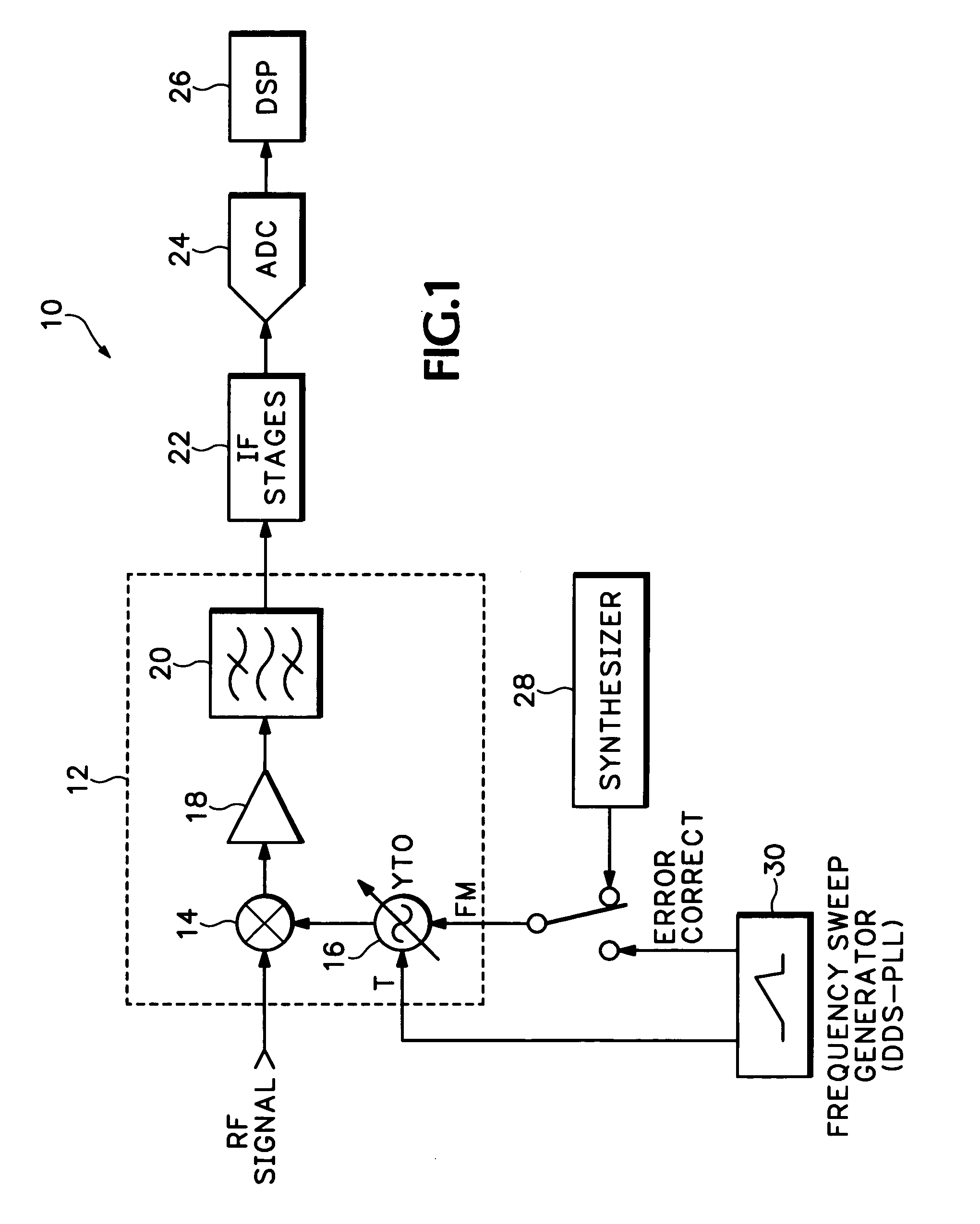
[0010]The typical spectrum analyzer 10 shown in FIG. 1 includes an input mixing stage 12 that receives an input RF signal at a first mixer 14 to which also is input a frequency signal from a YTO 16. The frequency converted signal is input to an amplifier 18 and subsequently filtered by a bandpass filter 20 to produce a first IF signal. The first IF signal is processed by subsequent IF mixing stages 22 before being digitized by an ADC 24. The digitized signal is then processed by a DSP 26. According to prior techniques the YTO 16 is controlled by a synthesizer 28 or similar control signal generator. However for wide frequency spans an alternative sweep generator 30 is shown which uses the DDS-PLL technique together with digital synthesis of a ramp control signal as described below.

[0011]Referring now to FIG. 2 the DDS-PLL sweep generator 30 is shown having a direct digital synthesizer (DDS) 32 that is clocked by a DDS clock. The DDS 32 is operated in a frequency shift keying (FSK) mo...


PUM


Abstract

A high frequency sweep generator uses a DDS-PLL method for frequency sweep over wide frequency spans. A digital sweep generator produces a linear ramp signal using DDS techniques that is applied to a coarse tuning port of a high frequency tunable oscillator, such as a YIG tunable oscillator (YTO). A PLL has as inputs an accurate linear swept frequency sinusoid from a DDS and a linear swept frequency output signal from the YTO to produce an error correction signal that is applied to a fine tuning port of the high frequency tunable oscillator. The error correction signal compensates for any non-linearities introduced into the linear swept frequency output signal by the high frequency tunable oscillator.

Description

BACKGROUND OF THE INVENTION[0001]The present invention relates to analog and digital radio frequency (RF) control techniques, and more particularly to a direct digital systhesizer (DDS)—phase locked loop (PLL) method for frequency sweep that generates and controls accurate and linear wideband frequency sweeps in an analog frequency control section of RF and microwave swept real-time spectrum analyzers.[0002]Generating an accurate linear wideband frequency sweep in swept microwave spectrum analyzers has historically been hindered by a number of nuisance problems. The swept oscillator in these instruments is traditionally a yttrium-iron-garnet (YIG) tuned oscillator (YTO). These oscillators generally have a tuning port for coarse frequency tuning and an FM port for fine frequency tuning. For narrow frequency spans the voltage at the tuning port is held constant and a small ramp signal is applied to the FM tuning port. For wide frequency spans the voltage at the FM tuning port is held ...

Claims


Application Information

Patent Timeline
Patent Type & Authority Patents(United States)
IPC IPC(8): H04B1/06H03B23/00H03L7/18
CPCH03B23/00H03L7/18H03L2207/06
Inventor RATHBUN, JR., LOWELL A.
Owner TEKTRONIX INC
Learn More