
Hydraulic system for heavy equipment option apparatus

a technology of heavy equipment and hydraulic system, which is applied in mechanical equipment, couplings, constructions, etc., can solve the problems of increasing the size of the corresponding part, the addition of work processes, and the increase of fabrication costs, so as to reduce the unit cost and the fabrication cost

Active Publication Date: 2007-01-02
VOLVO CONSTR EQUIP
View PDF7 Cites 4 Cited by
  • Summary
  • Abstract
  • Description
  • Claims
  • Application Information

AI Technical Summary

Benefits of technology

[0008]Accordingly, it is an object of the present invention to provide a hydraulic system for a heavy equipment option apparatus which is capable of implementing a small and compact size control valve assembly and decreasing a unit cost and a fabrication cost in such a manner that an operation oil is supplied to an option apparatus without changing a structure of a control valve assembly in the case that an option apparatus is additionally engaged to a small size excavator of a crawler type.

Problems solved by technology

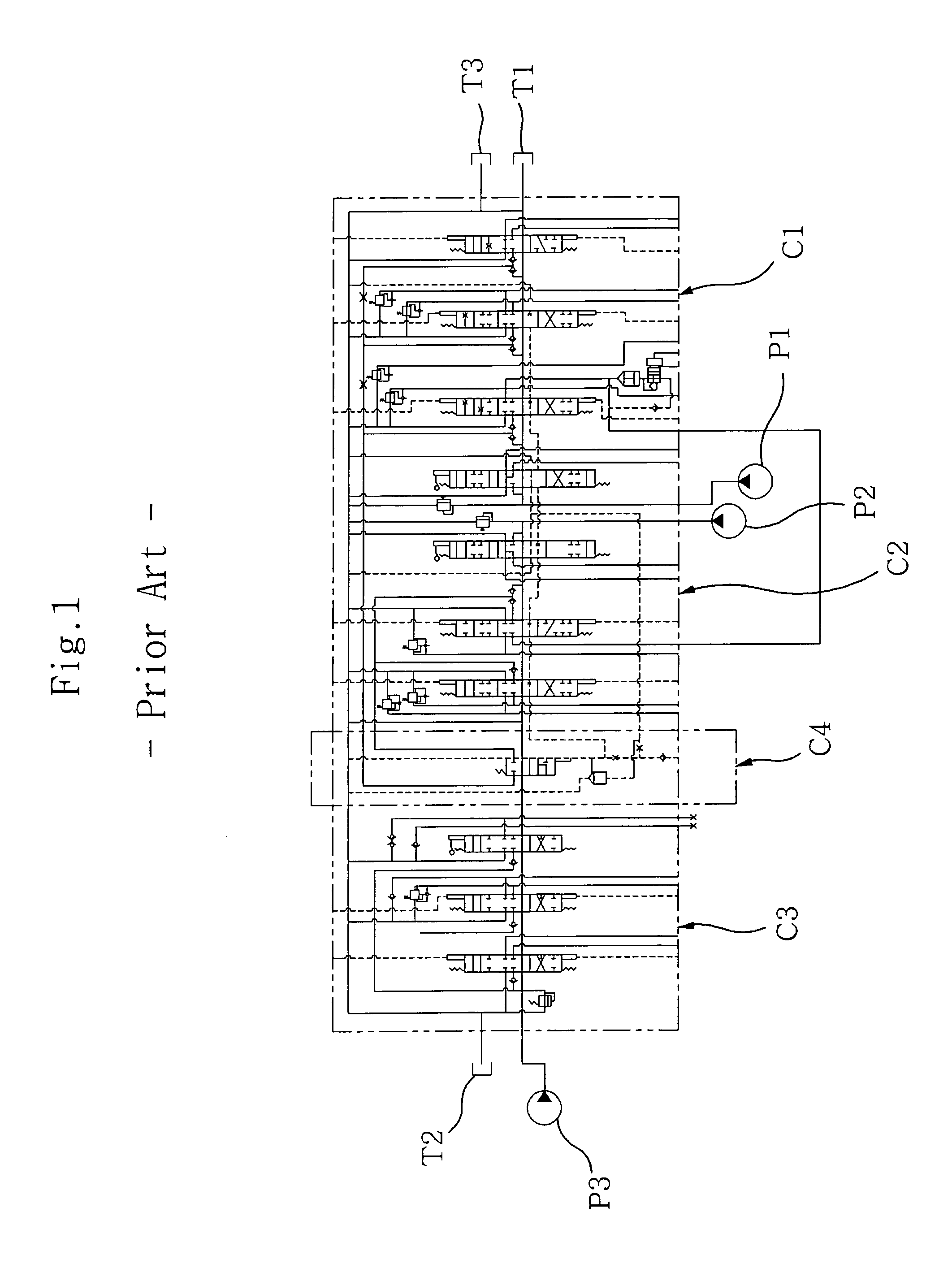
However, in the case that an operation is implemented by an operation oil from the third hydraulic pump P3 by additionally engaging an option apparatus to a small excavator to which a conventional hydraulic system is adapted, since an additional switching apparatus capable of supplying an operation oil to an additional option apparatus is attached to a front or rear portion of the straight traveling control valve C4 or a design of a control valve structure should be changed, a size of a corresponding part is increased, and a work process is added, so that a fabrication cost is increased.
In addition, in order to engage a control valve assembly having a large outer size to a small size excavator, a substantial space is required, and a workability that a large size control valve assembly is engaged to a small space of a small size excavator is decreased.

Method used


Image

  • Hydraulic system for heavy equipment option apparatus
  • Hydraulic system for heavy equipment option apparatus
  • Hydraulic system for heavy equipment option apparatus

Examples


Embodiment Construction

[0017]The preferred embodiment of the present invention will be described in detail with reference to the accompanying drawings.

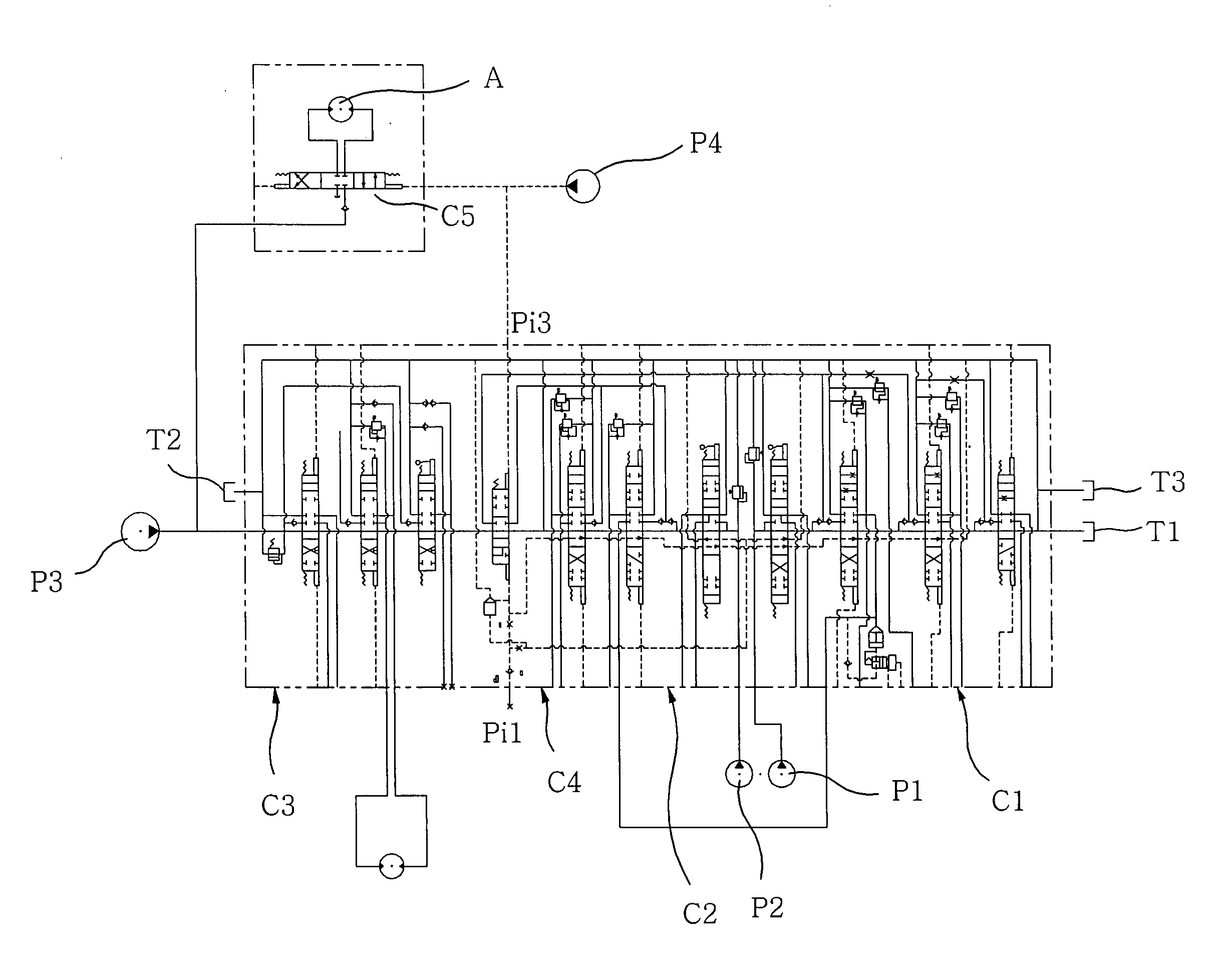
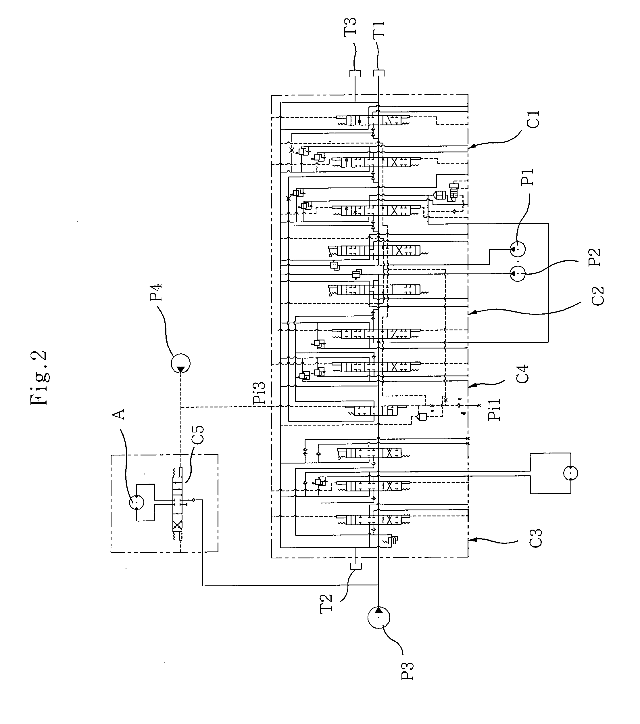
[0018]As shown in FIGS. 2 through 4, the present invention is adapted to a heavy equipment hydraulic system which includes a plurality of hydraulic pumps P1, P2 and P3, a plurality of control valves C1, C2 and C3 which are switched by a pilot signal pressure Pi and supply an operation oil from the hydraulic pumps P1, P2 and P3 to a left and right side traveling motor or work apparatus, and a pilot pump (not shown) which supplies a switching pilot signal pressure to the main control valves C1, C2 and C3. Since the above construction is the same as FIG. 1, the detailed construction and operation will be omitted.

[0019]Therefore, a hydraulic system for a heavy equipment option apparatus according to the present invention includes a straight traveling control valve C4 which combines an operation oil from the hydraulic pumps P2 and P3 when it is switched by a sup...


PUM


Abstract

The present invention is directed to controlling an operation oil supplied to an option apparatus without changing a design of a control valve assembly which controls an operation oil supplied to a traveling motor, etc. when additionally engaging an option apparatus to a small size excavator. In a hydraulic system for a heavy equipment which includes a plurality of hydraulic pumps, a main control valve which is switched by a pilot signal pressure and controls an operation oil supplied to a left and right side traveling motor and a work apparatus, and a pilot pump which supplies a pilot signal pressure to the main control valve, there is provided a hydraulic system for a heavy equipment option apparatus which includes a straight traveling control valve which combines an operation from a plurality of the hydraulic pumps and supplies to the left and right side traveling motors and disconnects an operation supplied to the traveling motor when the same is switched by a pilot signal pressure, and an option apparatus control valve which is switched concurrently with the straight traveling control valve by a pilot signal pressure and controls an operation oil supplied from one side hydraulic pump to an additional option apparatus.

Description

BACKGROUND OF THE INVENTION[0001]1. Field of the Invention[0002]The present invention relates to a hydraulic system for a heavy equipment option which is capable of implementing a certain work by switching an option apparatus using a conventional straight traveling control valve when an option apparatus (referred to a braker) is additionally engaged to a small size excavator, and in particular to a hydraulic system for a heavy equipment option which is capable of controlling an operation oil which is supplied to an option apparatus by a switching apparatus switched together with a straight traveling control valve in a state that a design of a control valve assembly which controls an operation oil supplied to a traveling motor or a work apparatus in the case that an option apparatus is additionally engaged to a small size excavator of a crawler type.[0003]2. Description of the Background Art[0004]As shown in FIG. 1, a conventional hydraulic system of a heavy equipment includes a firs...

Claims


Application Information

Patent Timeline
IPC IPC(8): F16D31/02E02F9/20E02F9/22F15B11/16F15B11/17
CPCE02F9/2267E02F9/2292F15B11/16F15B11/17F15B2211/71F15B2211/30595F15B2211/3116F15B2211/329F15B2211/20576E02F9/2264E02F9/20
Inventor JEON, MAN SUK
Owner VOLVO CONSTR EQUIP
Learn More