
Method of making complex twisted blades with hollow airfoil cross section and the turbines based on such

a technology of hollow airfoil and complex twisted blades, which is applied in the direction of wind motors with perpendicular air flow, liquid fuel engine components, non-positive displacement fluid engines, etc., can solve the problem of prohibitively high-efficiency turbines and achieve the effect of high efficiency

Inactive Publication Date: 2007-01-02
GCK
View PDF12 Cites 50 Cited by
  • Summary
  • Abstract
  • Description
  • Claims
  • Application Information

AI Technical Summary

Benefits of technology

[0004]The present invention satisfies a long-standing need for a method by which the high efficiencies of modern turbines, made possible by the utilization of complex aerodynamic blade designs, may be approximated with conventional manufacturing resources. Such approximations of modern blades can approach the efficiencies available to industrialized economies at a cost affordable in struggling economies such as those of third-world nations. In addition to initial affordability, the present invention's conception of blades made of discrete sections makes it possible to repair turbine blades at a cost much lower than would be required for replacement of expensive molded or cast blades.

Problems solved by technology

Advances in aerodynamics and materials science have increased the efficiency and decreased the weight and friction of these devices, and concomitantly increased their usefulness.
Until demand drives production to very high levels, such manufacturing requirements make high-efficiency turbines prohibitively expensive, particularly in developing nations where wind and water could provide much-needed power sources.

Method used


Image

  • Method of making complex twisted blades with hollow airfoil cross section and the turbines based on such
  • Method of making complex twisted blades with hollow airfoil cross section and the turbines based on such
  • Method of making complex twisted blades with hollow airfoil cross section and the turbines based on such

Examples


Embodiment Construction

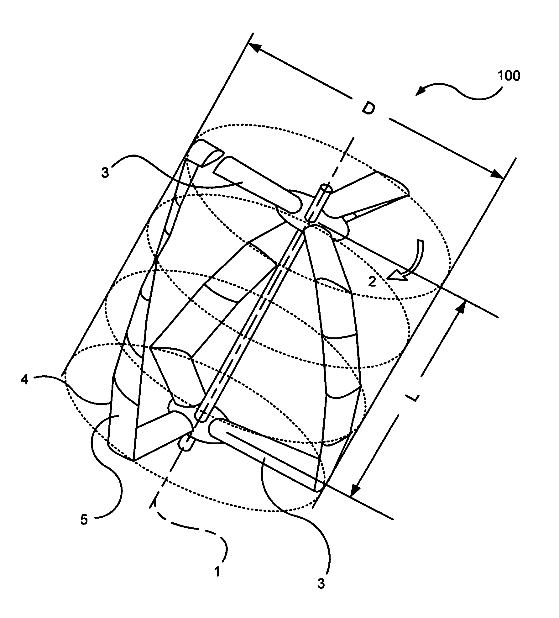
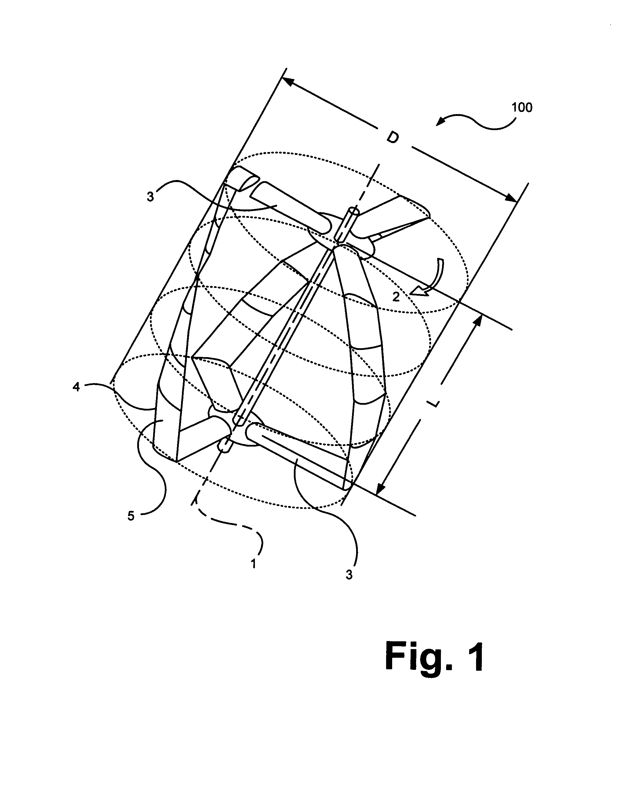
[0019]A first embodiment 100 of the invention is shown in FIG. 1. Three turbine blades, each comprised of four blade members 5, span the turbine longitudinal dimension L between three lower and three upper blade support members 3 of turbine 100 having an axis of rotation 1, a diameter D, and a direction of rotation 2 in the direction of the blade members' leading edges 4.

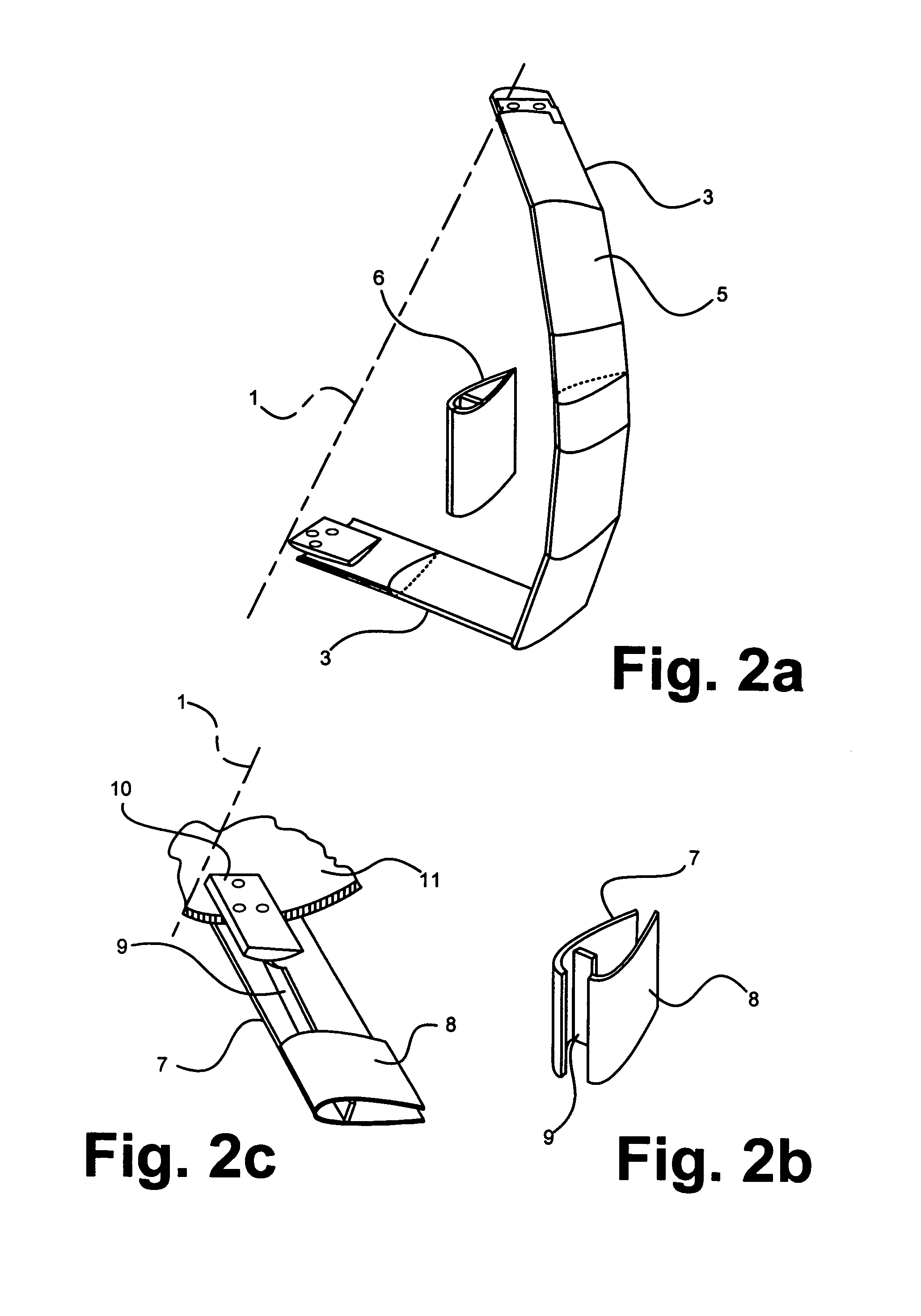
[0020]Construction details of one embodiment of one blade of the invention are shown in FIGS. 2a, b, and c. The two blade support members 3 and four blade members 5 of a single turbine blade are shown in FIG. 2a positioned on turbine axis of rotation 1. FIG. 2a shows a blade member filled with foam 6. FIG. 2b shows the upper and lower parts 7 and 8 and a spacer 9 of a blade member as it might be assembled from separate pieces of sheet metal. FIG. 2c shows how a blade support member 3 might be constructed from two metal sheets 7 and 8, a spacer 9, and a connector block 10 that attaches blade support member 3 to a hub...


PUM

PropertyMeasurementUnit
angleaaaaaaaaaa
lengthaaaaaaaaaa
plasticaaaaaaaaaa

Abstract

A reactive turbine, each blade of which approximates a helical shape that is constructed with readily available conventional manufacturing techniques. The blades are constructed in discrete straight sections that, when joined, approximate a helix or any other efficient turbine shape. Each section is manufactured with the well known and readily available machine shop techniques of shaping, forming, and joining with welds or fasteners.

Description

FIELD OF THE INVENTION[0001]The present invention pertains to the field of unidirectional reaction turbines capable of operation under the influence of reversible fluid flows.BACKGROUND OF THE INVENTION[0002]Wind and water-driven devices have been used for centuries for conversion of naturally occurring phenomena into useful power. Advances in aerodynamics and materials science have increased the efficiency and decreased the weight and friction of these devices, and concomitantly increased their usefulness. Turbine blades have progressed from primitive paddle wheels to space-age shapes with complex compound curves that require sophisticated manufacturing techniques such as numerically-controlled laser cutting, composite molding, casting, and powder metallurgy. Until demand drives production to very high levels, such manufacturing requirements make high-efficiency turbines prohibitively expensive, particularly in developing nations where wind and water could provide much-needed power...

Claims


Application Information

Patent Timeline
Patent Type & Authority Patents(United States)
IPC IPC(8): F03D7/06B23P15/04F01D5/14F03D3/06
CPCB23P15/04F03D3/062F05B2240/211Y10T29/49321Y02E10/74Y10S415/907F05B2250/25Y02P70/50
Inventor PALLEY, IGOR
Owner GCK
Learn More