Choke coil and electronic device using the same

Inactive Publication Date: 2007-01-02
PANASONIC CORP
View PDF6 Cites 7 Cited by
  • Summary
  • Abstract
  • Description
  • Claims
  • Application Information

AI Technical Summary

Benefits of technology

[0008]a radiator of a material with excellent thermal con

Problems solved by technology

Furthermore, a supply capacity of a few to a few tens amperes of high current is desired in a high frequency band responding to the realization of high speed and high integration of LSIs such as a CPU, which causes a problem of heat generation from the CPU and the choke coil.
However

Method used


Image

  • Choke coil and electronic device using the same
  • Choke coil and electronic device using the same
  • Choke coil and electronic device using the same

Examples


Example

(Embodiment 1)

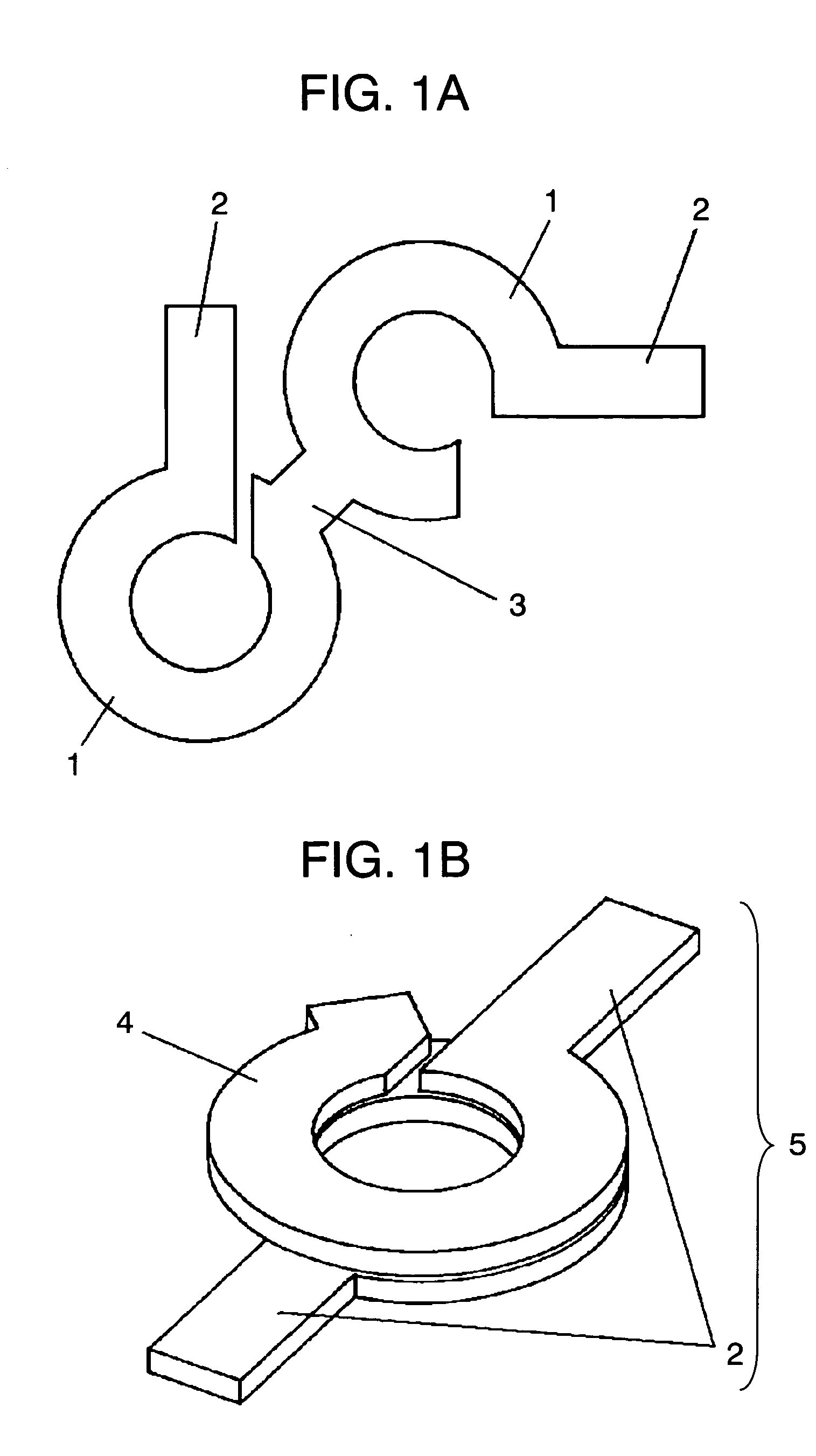
[0022]First, as shown in FIG. 1A, a coil incorporated with terminals is formed by etching or punching a metal plate such as copper and silver, which is formed of two circular disks 1 cut into a ring shape and two terminals 2 extended therefrom.

[0023]This punched plate is folded at a fold 3 where the circular disks 1 are connected so as to overlay the center points each other. Thus, as shown in FIG. 1B, a plurality of the circular disks 1 becomes a coil portion 4, and the two terminals 2 are disposed radially to the center of the coil portion 4 for forming a coil incorporated with terminals 5.

[0024]In addition, the number of turns of the coil 5 incorporated with terminals is not integers in particular, it is freely set to 1.5 turn and 1.75 turn as similar to the traditional coil; the size and the inductance value are the same.

[0025]An insulation layer 6 is provided on the circular disks 1 forming the coil portion 4 for avoiding short circuits. On this account, the circu...

Example

(Embodiment 2)

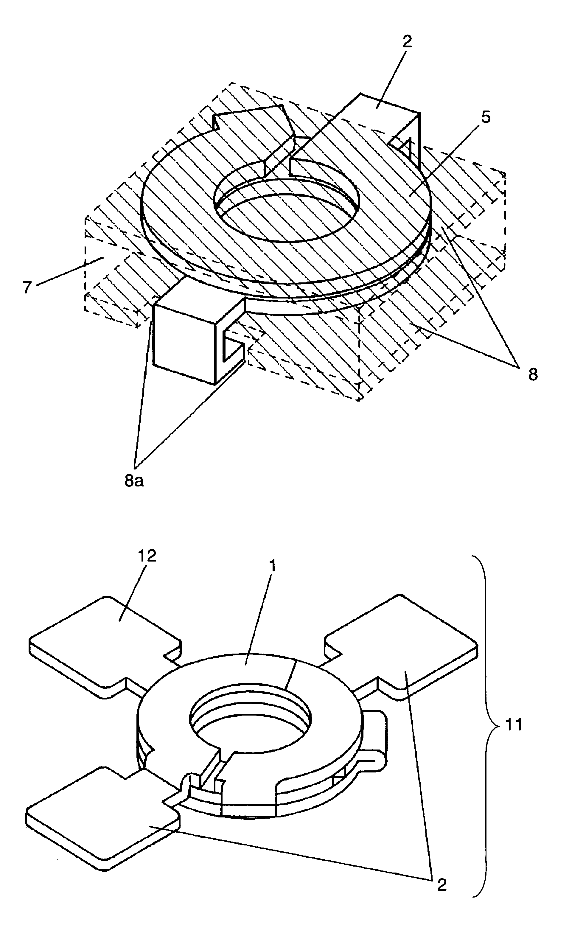
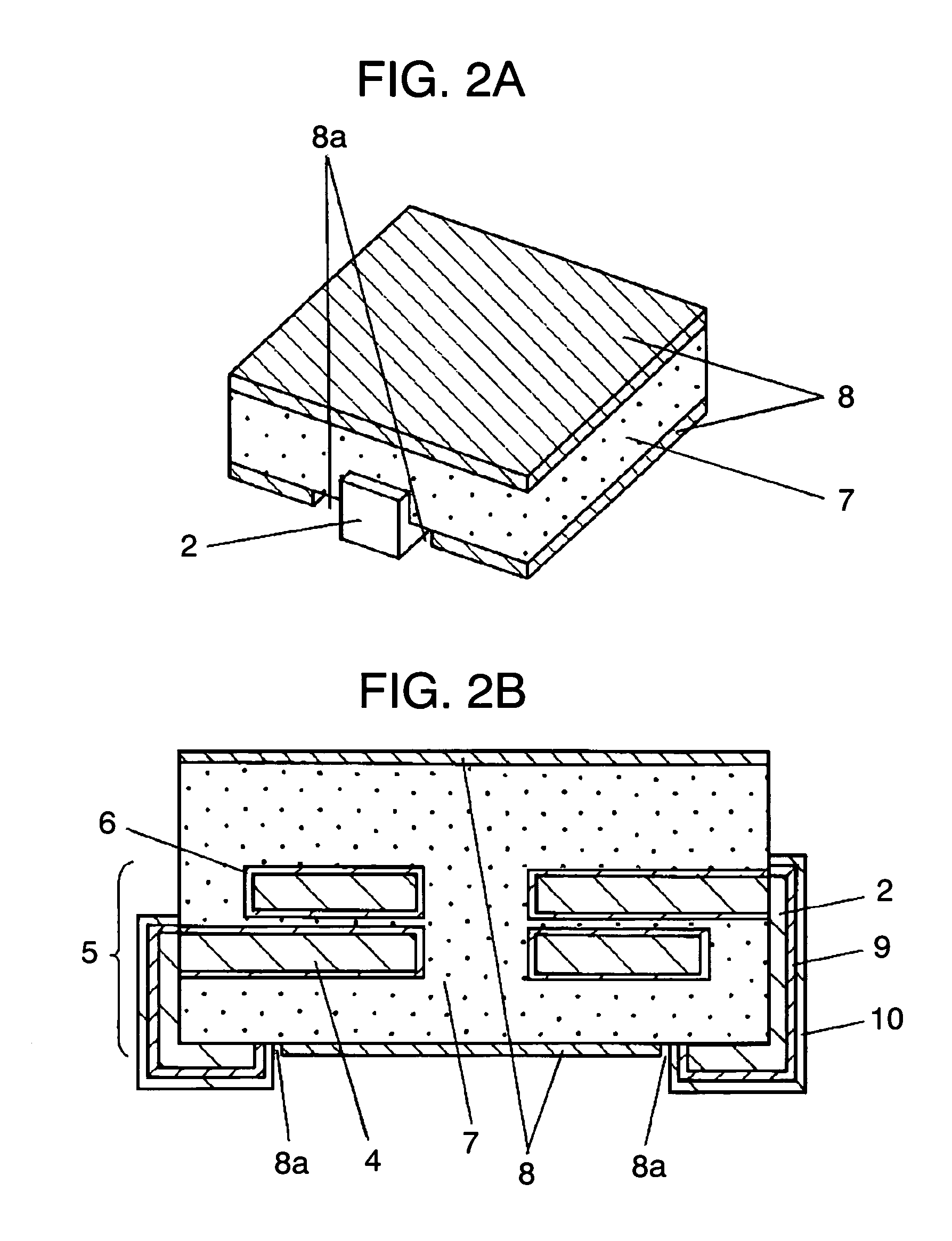
[0044]FIG. 4A is a perspective view illustrating a choke coil of Embodiment 2, and FIG. 4B is a cross-sectional view illustrating the same. A coil 11 incorporated with intermediate tap and terminals is formed in which a radiator 8 is buried in the surface of a magnetic material 7 having the coil 11 therein so that the radiator 8 is spread radially from the position corresponding to the air core part of the coil 11 and is extended to the side surface of the magnetic material 7.

[0045]As shown in FIG. 5, the coil 11 incorporated with intermediate tap and terminals is formed in which an intermediate tap 12 is projected from one of the plurality of the circular disks 1 of the coil 5 incorporated with terminals according to Embodiment 1.

[0046]The other configurations are the same as those of Embodiment 1.

[0047]Hereinafter, advantages of the configuration will be described.

[0048]In the choke coil of Embodiment 2, the radiator 8 is formed radially so that it is extended from t...

Example

(Embodiment 3)

[0050]FIG. 6A is a perspective view illustrating a choke coil of Embodiment 3, and FIG. 6B is a cross-sectional view illustrating line 6B—6B shown in FIG. 6A. A radiator 8 is formed on the top surface and two adjacent side surfaces of a magnetic material 7 having two coils 5 incorporated with terminals buried therein side by side, and a plurality of slits 13 is disposed in the radiator 8 at fixed intervals. The other configurations are the same as those of Embodiment 1.

[0051]According to this configuration, air flows along the slits 13 to allow quickly lowering heat by air cooling.

[0052]Furthermore, the slits 13 are disposed in the radiator 8 only on the top surface and the two adjacent side surfaces at fixed intervals in Embodiment 3, but hey can be formed any surfaces of the magnetic material 7 in accordance with the arrangement of a circuit board and devices to be mounted.

[0053]Moreover, any orientations and intervals are fine in the slits 13, they can be determined...


PUM


Abstract

A choke coil according to the invention is configured to include: a coil incorporated with terminals and/or intermediate tap, the coil configured of a metal plate being punched and folded; a magnetic material buried with the coil therein; and a radiator of a material with excellent thermal conductivity disposed on a surface of the magnetic material. A small-sized, low-profile choke coil structurally stable with excellent heat dissipation is to be provided.

Description

FIELD OF THE INVENTION[0001]The present invention relates to a choke coil usable for a DC / DC converter mounted on various electronic devices, and an electronic device using the same.BACKGROUND OF THE INVENTION[0002]In recent years, the realization of reduction in the size and thickness of choke coils themselves is demanded with the further progress of the realization of reduction in the size and thickness of electronic devices. Furthermore, a supply capacity of a few to a few tens amperes of high current is desired in a high frequency band responding to the realization of high speed and high integration of LSIs such as a CPU, which causes a problem of heat generation from the CPU and the choke coil.[0003]In traditional winding inductance components, the heat problem like this is tried to be solved by tightly forming a resin material with high heat dissipation around a core and a winding to cover them with a case of a material with high thermal conductivity (see JPH4-267313, page 73,...

Claims


Application Information

Patent Timeline
IPC IPC(8): H01F27/08H01F21/12H01F27/02H01F27/255H01F27/29H01F37/00
CPCH01F27/027H01F27/292H01F21/12H01F2027/2861H01F2017/046H01F2017/048H01F37/00
Inventor MATSUTANI, NOBUYAIMANISHI, TSUNETSUGUUEMATSU, HIDENORI
Owner PANASONIC CORP
Why Eureka
Try Eureka