Communication terminal

a terminal and communication technology, applied in the field of communication terminals, can solve the problems of antenna snagged on the edge, radiation effect deterioration, antenna collapse, etc., and achieve the effect of reducing the amount of electromagnetic wave absorbed

a terminal and communication technology, applied in the field of communication terminals, can solve the problems of antenna snagged on the edge, radiation effect deterioration, antenna collapse, etc., and achieve the effect of reducing the amount of electromagnetic wave absorbed

US7158083B2Inactive Publication Date: 2007-01-02PANASONIC CORP

Image

  • Communication terminal
  • Communication terminal
  • Communication terminal

Examples


Embodiment Construction

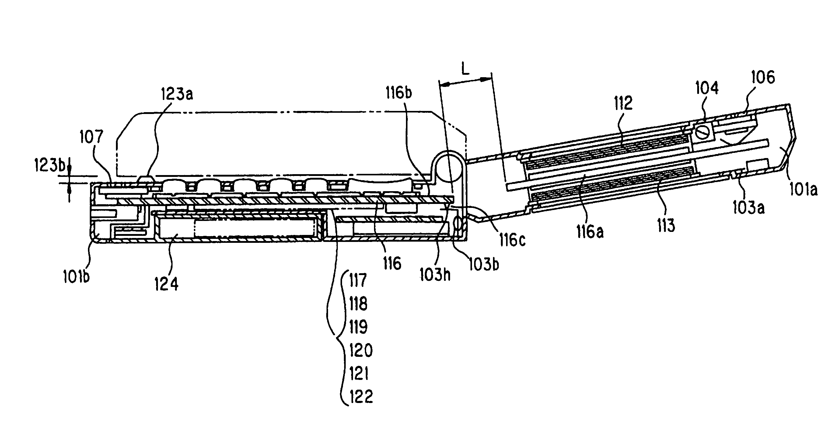
[0050]Embodiments of the foldable communication terminal according to the invention are described below referring to drawings. While the communication terminal is described as a foldable cell phone supporting both the W-CDMA (Wideband Code Division Multiple Access) system and the GSM (Global System for Mobile Communication), the invention is applicable to other foldable communication terminals also.

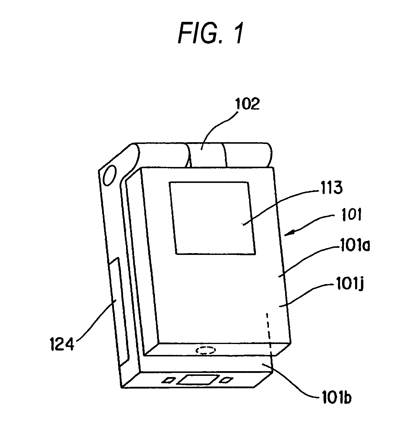
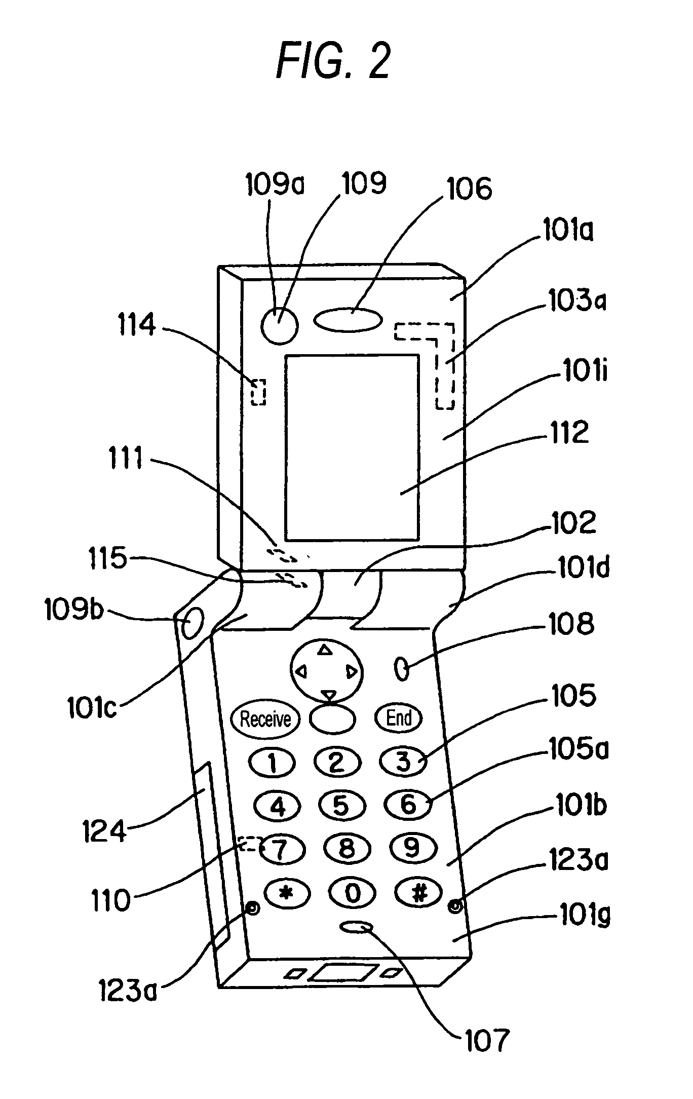
[0051]FIG. 1 is a perspective view of a foldable communication terminal according to an embodiment of the invention in a closed state. FIG. 2 is a perspective view of a foldable communication terminal according to an embodiment of the invention in a first opened state. FIG. 3 is a perspective view of a foldable communication terminal according to an embodiment of the invention in a second opened state. FIG. 4 is a perspective view of a foldable communication terminal according to an embodiment of the invention in a third opened state. FIG. 5 is an external view the communication terminal ...


PUM


Abstract

The invention aims at providing a communication terminal capable of suppressing degradation of an antenna gain irrespective of whether the casing of the communication terminal is opened or closed. The communication terminal includes a hinge for coupling in a foldable manner a first casing member and a second casing member, each including conductors such as a first printed board and a second printed board. In close proximity to the hinge in the second casing member is provides a second antenna. The hinge includes a first rotation axis composed of a conductive metal material working as an axis of rotation of two casing members in opposite directions and a second rotation axis composed of a conductive metal material working as an axis of rotation in a direction orthogonal to the direction of rotation about the first rotation axis. A predetermined clearance L to place the conductors of the first and second casing members in capacity coupling is formed and the hinge is insulated from the conductor of one of the two casing members.

Description

[0001]This application is a 371 of PCT / JP03 / 12908 Oct. 8, 2003.TECHNICAL FIELD[0002]The present invention relates to a communication terminal having foldable casings, and in particular to a casing structure of a communication terminal equipped with an antenna for transmitting / receiving a radio signal.BACKGROUND ART[0003]A first example of a prior art foldable communication terminal is one described in Patent Document 1. The prior art foldable communication terminal is described below referring to drawings. FIG. 20 shows the structure of a prior art communication terminal and the principle of operation of the antenna provided thereon. FIG. 20A shows a state where the casings are closed and FIG. 20B a state where the casings are opened. In FIGS. 20A and 20B, the communication terminal includes a first casing 202 connected to a telescopic antenna 201 and a second casing 203 positioned on the side of the antenna, the second casing including a metal material or a material including a met...

Claims


Application Information

Patent Timeline
02 Jan 2007
Publication
US7158083B2
IPC
H01Q1/24; H01Q1/36; H01Q1/08; H01Q3/08; H01Q5/10; H01Q9/16; H01Q9/32; H04M1/02
CPC
H01Q1/084; H01Q1/242; H01Q1/244; H01Q3/08; H04M1/0241; H01Q9/32; H04M1/0212; H01Q9/16
Inventors
SATOH, NORIYOSHI; SATO, KENICHI