Methods and apparatus for thermal management of an integrated circuit die

a technology of thermal management and integrated circuits, applied in the direction of instruments, heat measurement, sustainable buildings, etc., can solve the problems of reducing the service life of the heat management system, and pushing the conventional thermal management technology to its limit, etc. performance and reliability suffers or cannot be guaranteed

Inactive Publication Date: 2007-01-02
SONY CORP OF AMERICA
View PDF48 Cites 46 Cited by
  • Summary
  • Abstract
  • Description
  • Claims
  • Application Information

AI Technical Summary

Problems solved by technology

As a result, these microprocessors exhibit high power dissipation and, hence, a corresponding heat load requiring increased cooling capacity, and these high cooling requirements are pushing conventional thermal management technology to its limit.
If adequate heat transfer does not occur, the die temperature may achieve a level at which performance and reliability suffer or can no longer be guaranteed and, if unchecked, a die temperature may be reached at which permanent structural damage to the microprocessor occurs.
The power dissipation of a microprocessor may, however, cause uneven heating of the die.
Also, with the advent in recent years of microprocessors possessing high speed and performance, there has been increasing disparity between typical power—i.e., the power consumed when running normal applications, such as those run on a personal computer—and maximum power—i.e., the power consumed while running a synthetic, high-power workload specifically designed for maximum power consumption.
Thus, although a microprocessor may rarely, if ever, achieve maximum power for an extended period, techniques for thermal management of microprocessors may, in some instances, target the maximum power level to insure that die temperatures will not exceed thermal design limits during operation, potentially causing heat-induced failure or damage to the microprocessor.
For example, it is common to thermally couple a heat sink or heat pipe, or other liquid cooling element, to a semiconductor die; however, such passive components possess a limited capacity to dissipate heat.
There are, however, several disadvantages associated with the use of fans for cooling IC devices, including poor reliability compared to semiconductor devices, noise, and space requirements.
Also, active devices such as fans, as well as the above-described passive device, are generally over-designed for typical power dissipation in order to address the worst case scenario—i.e., the dissipation of maximum power.
Such thermal monitoring systems are inherently inaccurate due to poor thermal coupling (i.e., a thermal time delay) between the sensor and die.
Also, the off-chip control hardware requires the addition of other components to the IC device being sensed or to the next-level assembly, and these added components may consume more surface area in the next-level assembly (i.e., surface area of a circuit board) than the IC device itself.
Although on-chip thermal sensors substantially eliminate the inherent latency of the separately-attached thermal sensor, currently available sensor control and interface logic does not provide reliable temperature measurement and / or closed-loop thermal control.
A lack of integration amongst the various elements comprising the conventional sensor control and interface logic, as well as poor integration with the IC device itself, provide a thermal management system exhibiting insufficient response time and, hence, unreliable temperature control.
However, the increasing speed and circuit density of newer microprocessors will necessitate even lower supply voltages, but the electrical noise generally present in any system inherently limits the degree to which supply voltages may be further reduced.

Method used


Image

  • Methods and apparatus for thermal management of an integrated circuit die
  • Methods and apparatus for thermal management of an integrated circuit die
  • Methods and apparatus for thermal management of an integrated circuit die

Examples


Embodiment Construction

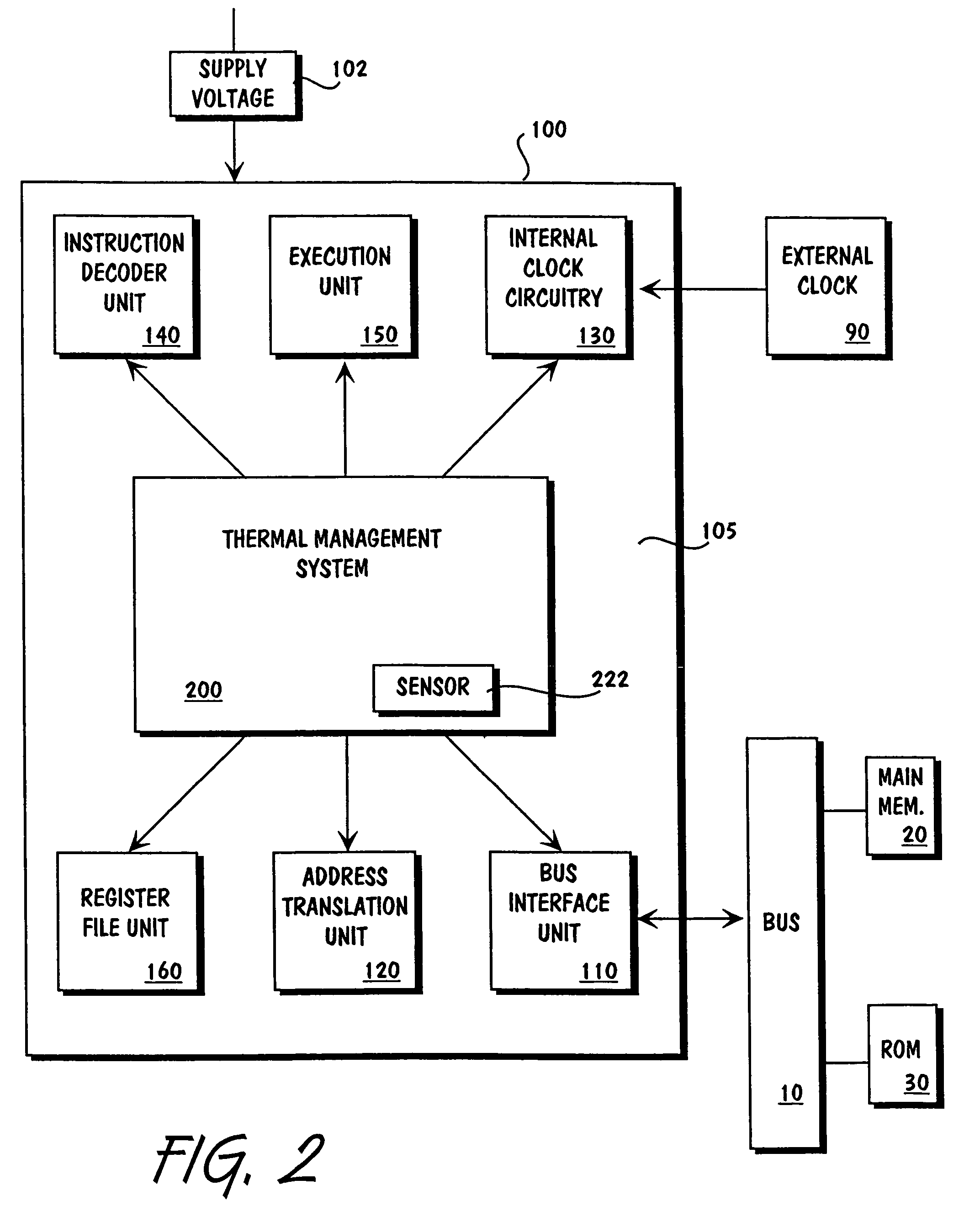
[0017]The above-noted deficiencies of prior art thermal management techniques are overcome by providing a tightly integrated thermal management system entirely contained on a semiconductor die, such as a microprocessor. Although illustrated below in the context of thermal management of a microprocessor, those of ordinary skill in the art will understand that the methods and apparatus described herein are generally applicable to all types of IC devices.

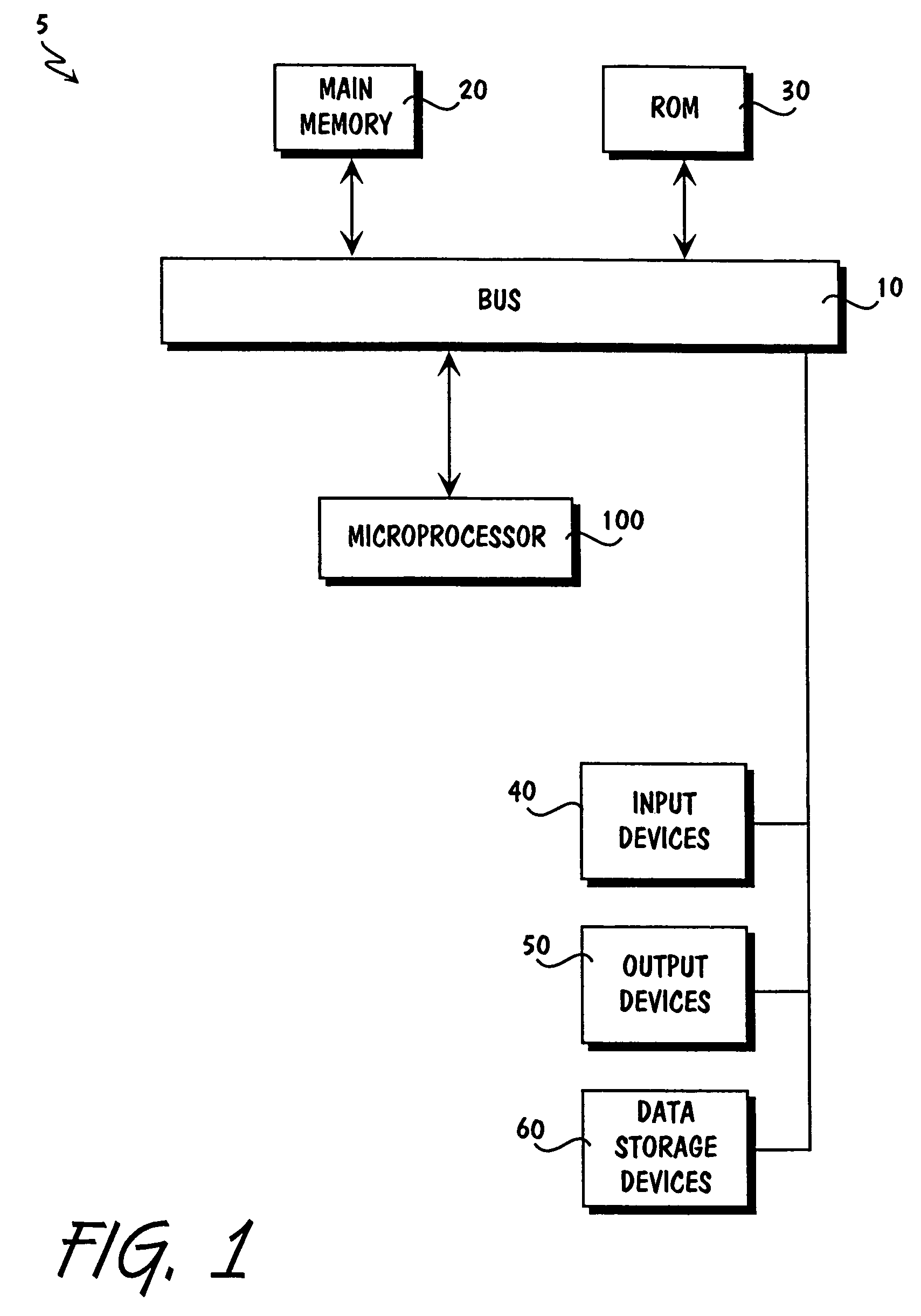
[0018]Shown schematically in FIG. 1 is a computer system 5 incorporating a microprocessor 100 providing on-chip, closed-loop thermal management. The microprocessor 100 is coupled via a bus 10 to main memory 20, which may comprise one or more dynamic random access memory (DRAM) devices for storing information and instructions to be executed by microprocessor 100. The main memory 20 may also be used for storing temporary variables or other intermediate information during execution of instructions by microprocessor 100. Computer system 5 ...


PUM

PropertyMeasurementUnit
temperatureaaaaaaaaaa
power consumptionaaaaaaaaaa
voltageaaaaaaaaaa

Abstract

An integrated, on-chip thermal management system providing closed-loop temperature control of an IC device and methods of performing thermal management of an IC device. The thermal management system comprises a temperature detection element, a power modulation element, a control element, and a visibility element. The temperature detection element includes a temperature sensor for detecting die temperature. The power modulation element may reduce the power consumption of an IC device by directly lowering the power consumption of the IC device, by limiting the speed at which the IC device executes instructions, by limiting the number of instructions executed by the IC device, or by a combination of these techniques. The control element allows for control over the behavior of the thermal management system, and the visibility element allows external devices to monitor the status of the thermal management system.

Description

CROSS-REFERENCE TO RELATED APPLICATIONS[0001]This application is a continuation of U.S. patent application Ser. No. 09 / 784,255, filed Feb. 14, 2001, now U.S. Pat. No. 6,789,037, which is a continuation-in-part of U.S. patent application Ser. No. 09 / 281,237, filed Mar. 30, 1999, now U.S. Pat. No. 6,393,374.FIELD OF THE INVENTION[0002]Thermal management of an integrated circuit die and, more specifically, integrated thermal management systems and methods of use for providing on-chip, closed-loop temperature control at one or more die locations.BACKGROUND OF THE INVENTION[0003]An integrated circuit (IC) device, such as a microprocessor, may include circuitry comprised of many types of discrete circuit components, including transistors, resistors, and capacitors, as well as other components. Semiconductor manufacturers are subject to ever-increasing pressure to increase the speed and performance of such IC devices while, at the same time, reducing package size and maintaining reliabilit...

Claims


Application Information

Patent Timeline
Patent Type & Authority Patents(United States)
IPC IPC(8): G01K1/08G01K7/01G06F1/20
CPCG01K7/015G06F1/206G06F1/3237G06F1/324G06F1/3296Y02B60/1285Y02B60/1217Y02B60/1221Y02B60/1275Y02D10/00
Inventor GUNTHER, STEPHEN H.BINNS, FRANKPIPPIN, JACK D.RANKIN, LINDA J.BURTON, EDWARD A.CARMEAN, DOUGLAS M.BAUER, JOHN M.
Owner SONY CORP OF AMERICA
Why Eureka
Try Eureka