
Manufacturing method for multilayer ceramic elements

a manufacturing method and ceramic element technology, applied in the direction of stacked capacitors, fixed capacitor details, semiconductor/solid-state device details, etc., can solve the problems of undesirable fracturing, often occurring undesirable fracturing along the breaking grooves b>2/b>, and causing undesirable fracturing of multi-layer integrated substrates b>1/b>, so as to prevent undesirable fracturing, the effect of effective prevention of undesirable fracturing

Inactive Publication Date: 2007-01-16
MURATA MFG CO LTD
View PDF9 Cites 5 Cited by
  • Summary
  • Abstract
  • Description
  • Claims
  • Application Information

AI Technical Summary

Benefits of technology

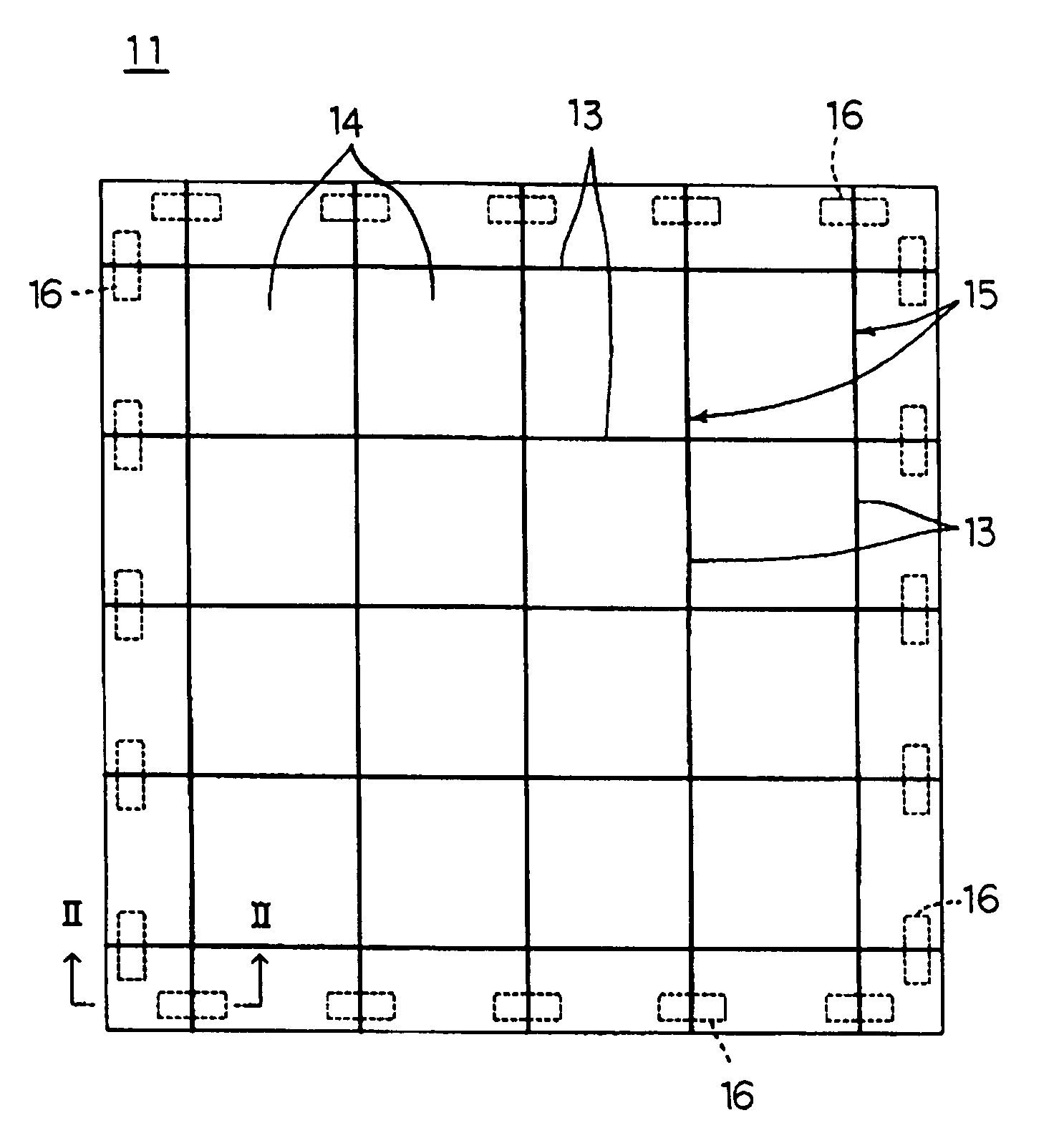
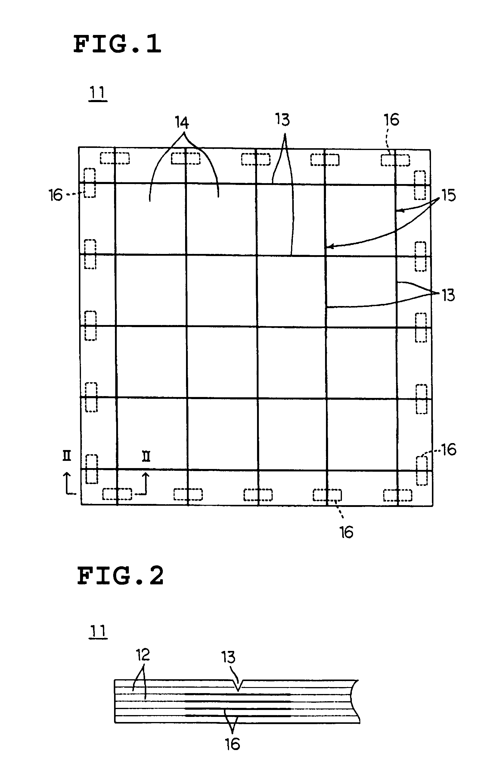
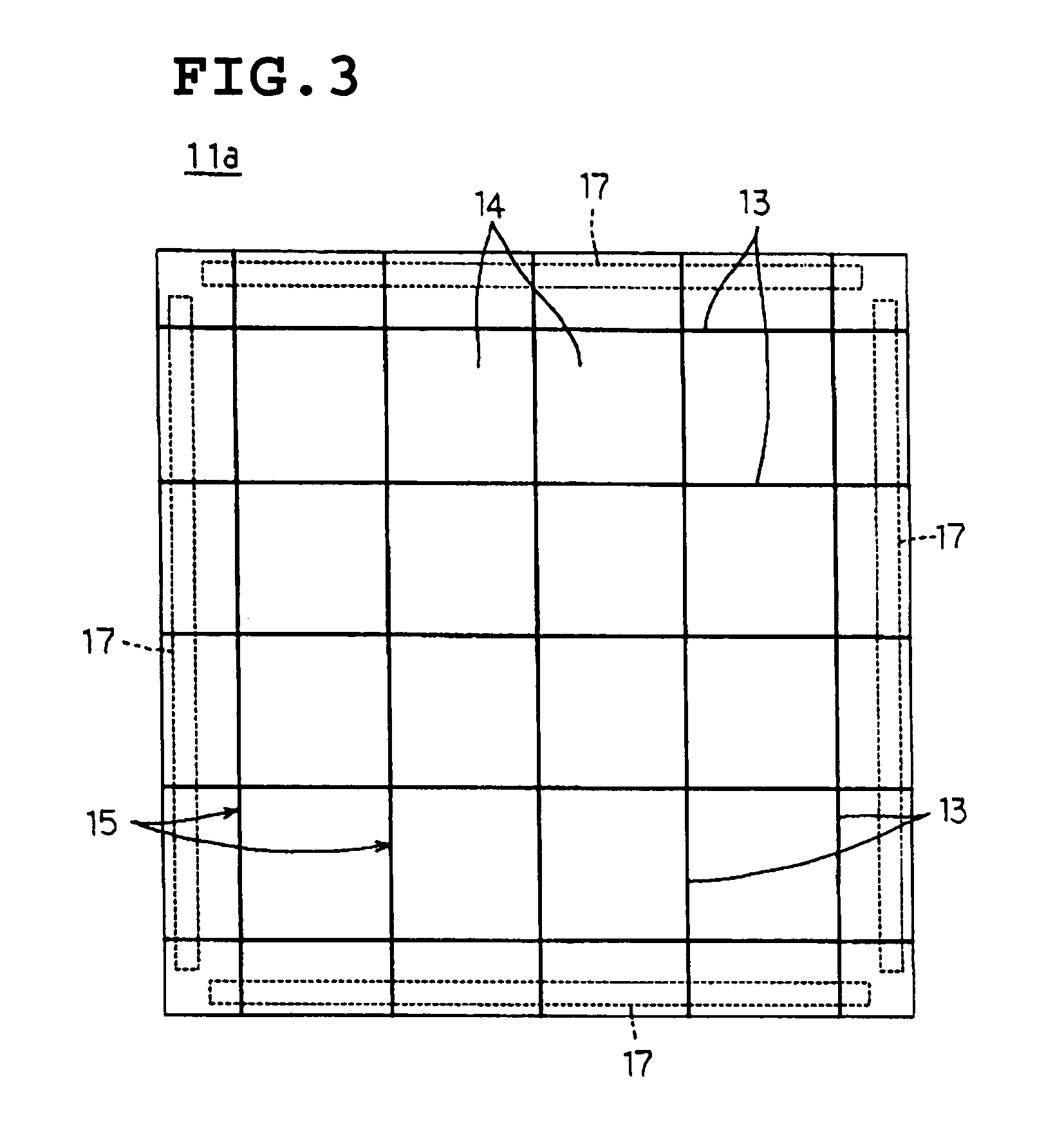
[0025]According to preferred embodiments of the present invention, the multilayer integrated substrate is provided with fracture-preventing members arranged to cross the breaking grooves, so that the strength thereof is increased. When the fracture-preventing conductors containing a metal component are used as the fracture-preventing members, undesirable fracturing of the multilayer integrated substrate along the breaking grooves is efficiently prevented due to ductility of the metal component.
[0039]In addition, the manufacturing process of the multilayer ceramic elements may include the step of mounting the electronic components on the blocks provided in the multilayer integrated substrate. In such a case, the conventional-type multilayer integrated substrate would easily be fractured along the breaking grooves in the step of mounting the electronic components. Such fracturing, however, is effectively prevented by using the multilayer integrated substrate of preferred embodiments of the present invention. Accordingly, the step of mounting other electronic components may be performed without any problems.

Problems solved by technology

When the thickness of the multilayer integrated substrate 1 is reduced as described above, however, undesirable fracturing of the multilayer integrated substrate 1 along the breaking grooves 2 often occurs.
Such undesirable fracturing is caused by, for example, pressure or heat applied to the multilayer integrated substrate 1 during the above-described processes such as mounting of components.
In extreme cases, the multilayer integrated substrate 1 may also be fractured due to nonuniform shrinkage in the firing process or thermal shock when the temperature decreases.

Method used


Image

  • Manufacturing method for multilayer ceramic elements
  • Manufacturing method for multilayer ceramic elements
  • Manufacturing method for multilayer ceramic elements

Examples


Embodiment Construction

[0051]FIG. 1 is a plan view schematically showing a multilayer integrated substrate 11 according to a preferred embodiment of the present invention. FIG. 2 is an expanded sectional view of FIG. 1 along line II—II.

[0052]The multilayer integrated substrate 11 is obtained by firing a laminate of a plurality of ceramic green sheets so as to have a laminated structure that includes a plurality of ceramic layers 12.

[0053]The multilayer integrated substrate 11 is provided with a plurality of breaking grooves 13 arranged in the main surface in a grid pattern. Multilayer ceramic elements 15 such as multilayer ceramic substrates are constructed in blocks 14 sectioned by the breaking grooves 13. Although not shown in the figure, the multilayer ceramic elements 15 are provided with electrical lines, etc.

[0054]The multilayer ceramic elements 15 can be obtained by breaking the multilayer integrated substrate 11 along the breaking grooves 13.

[0055]The blocks 14 in which the multilayer ceramic elem...


PUM

PropertyMeasurementUnit
Electrical conductoraaaaaaaaaa
Breaking strengthaaaaaaaaaa
Fractureaaaaaaaaaa

Abstract

A multilayer integrated substrate includes breaking grooves arranged in a grid pattern so as to section the main surface of the substrate into a plurality of blocks, and also includes fracture-preventing conductor films arranged so as to cross the breaking grooves. The fracture-preventing conductor films contain a metal component that prevents undesirable fracturing of the multilayer integrated substrate along the breaking grooves.

Description

[0001]This application is a Divisional of U.S. patent application Ser. No. 09 / 783,922 filed Feb. 15, 2001, now U.S. Pat. No. 6,621,010.BACKGROUND OF THE INVENTION[0002]1. Field of the Invention[0003]The present invention relates to a multilayer integrated substrate from which a plurality of multilayer ceramic elements are obtained, and also relates to a method of manufacturing the multilayer ceramic elements by using the multilayer integrated substrate. More specifically, the present invention relates to modifications for increasing the strength of the multilayer integrated substrate that includes breaking grooves for facilitating the process of breaking the multilayer integrated substrate to remove the multilayer ceramic elements.[0004]2. Description of the Related Art[0005]To increase manufacturing efficiency, multilayer ceramic elements such as multilayer ceramic substrates are often prepared in the form of a multilayer integrated substrate, and are obtained from the multilayer i...

Claims


Application Information

Patent Timeline
IPC IPC(8): H05K3/30H01G4/12H01G4/30H01L21/48H01L23/58H05K1/02H05K1/03H05K3/00H05K3/46
CPCH01L21/481H05K3/0052H01L23/585Y10T29/4913H05K1/0306H05K2201/09036H05K2201/0909H05K2201/09781H05K2203/302H01L2924/0002Y10T29/49165Y10T29/49126Y10T29/49163Y10T29/4979Y10T29/49789H01L2924/00
Inventor SAKAI, NORIOIIDA, KAZUHIRO
Owner MURATA MFG CO LTD
Learn More