
Control method and apparatus for gaseous fuelled internal combustion engine

a technology of internal combustion engine and control method, which is applied in the direction of electric control, mechanical equipment, machines/engines, etc., can solve the problems of increasing hydrocarbon emissions and combustion energy loss that could otherwise be utilized to drive the piston, natural gas impacting on such a hot surface will ignite and burn, etc., and achieves the effect of expanding the cross-sectional area

Inactive Publication Date: 2007-01-16
WESTPORT POWER
View PDF28 Cites 20 Cited by
  • Summary
  • Abstract
  • Description
  • Claims
  • Application Information

AI Technical Summary

Benefits of technology

"The patent describes methods and apparatus for assisting ignition and operation of gaseous-fueled internal combustion engines. The invention provides a method of preheating the intake charge of the engine and directing a pilot quantity of fuel into the combustion chamber during the compression stroke of the piston to raise the temperature of the intake charge and ignite the fuel. The method also includes injecting a second quantity of fuel during a power stroke to ignite and burn the fuel, and using a high-pressure injection valve to deliver a directed pilot quantity of fuel and a larger quantity of fuel for ignition. The invention improves engine performance under high-load conditions and allows for the use of natural gas or methane as the fuel."

Problems solved by technology

Natural gas impacting on such a hot surface will ignite and burn.
There are technical challenges associated with both approaches.
With hot surface ignition, if combustion is initiated at one point within the combustion chamber, incomplete combustion can occur resulting in increased hydrocarbon emissions and loss of combustion energy that could otherwise be utilized to drive the piston.
However, since flame propagation can be imperfect, gas directed into parts of the chamber furthest removed from the glow plug may fail to ignite or it may burn incompletely.
If flame propagation is not rapid enough to initiate combustion of gas within the combustion chamber, the directly injected quantities of natural gas may become too lean for ignition.
That is, a separate fuel supply system is needed, adding complexity in the engine.
Also, depending on the amount and type of pilot fuel, there may be undesirable emissions generated by combustion of the pilot fuel.
Further, a pilot fuel system adds cost to a natural gas engine.
There are the capital costs associated with the pilot fuel system as well as the maintenance time and costs for such maintenance.
However, spark ignition of a directly injected natural gas has many of the same challenges as glow plug ignition.

Method used


Image

  • Control method and apparatus for gaseous fuelled internal combustion engine
  • Control method and apparatus for gaseous fuelled internal combustion engine
  • Control method and apparatus for gaseous fuelled internal combustion engine

Examples


first embodiment

[0083]Accordingly, this first embodiment of the injection valve may be employed to carry out the method taught above.

[0084]The first embodiment of the injection valve requires the ability to accurately control the lift of valve needle 102. By way of example, a mechanical or hydraulic “latch” designed to control lift depending on the desired operating mode of the injection valve could be used. Such a latch might physically stop valve needle 102 from continuing beyond a certain point within the injection valve when actuated. Also, by way of example, as would be understood by a person skilled in the art, the lift of valve needle 102 may be controlled by a piezo-electric mechanism, a solenoid, a magneto-strictive device, or another type of mechanical device to allow for controlled lift of valve needle 102.

[0085]A feature of the first embodiment is the simplicity of the single monolithic needle design that controls flow through either pilot fuel nozzle orifice(s) 112 alone, or both pilot...

second embodiment

[0087]the fuel injection valve comprises needle tip 216 that is movable relative to valve needle 202. When valve needle 202 is in the closed position, actuator 217 allows needle tip 216 to retract within chamber 215 as shown in FIG. 8. For example, when actuator 217 is a spring member, the spring is compressed when the valve is in the closed position.

[0088]With reference now to FIG. 9, gaseous fuel can be injected into the combustion chamber through pilot fuel nozzle orifice(s) 212 when sealing surface 206 of valve needle 202 is lifted away from valve seat 204. Gaseous fuel is prevented from flowing from fuel cavity 208 to main fuel nozzle orifices 220 by an end face of needle tip 216 that is seated against secondary valve seat 214. Actuator 217 is expandable to bias the end face of needle tip 216 against secondary valve seat 214 when valve needle 202 is partially lifted. The partially open injection valve illustrated in FIG. 9 provides an apparatus for injecting fuel only through p...


PUM


Abstract

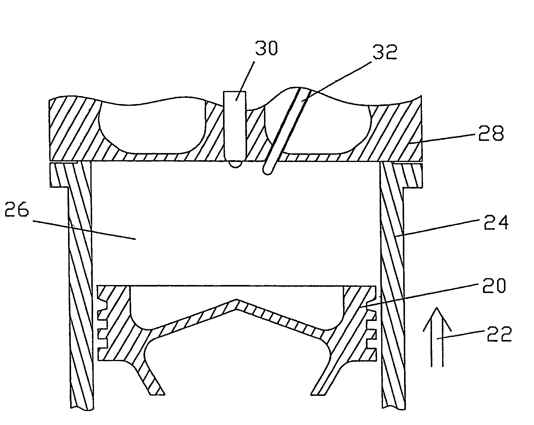
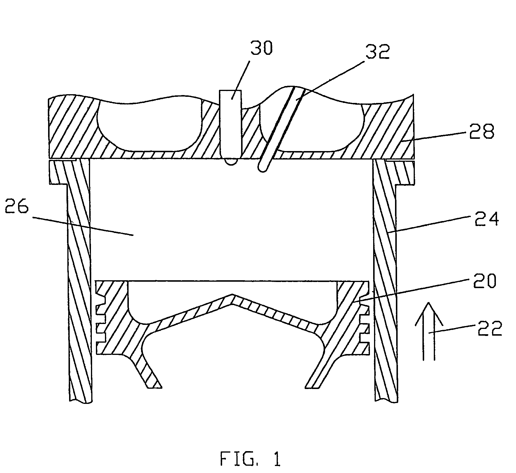
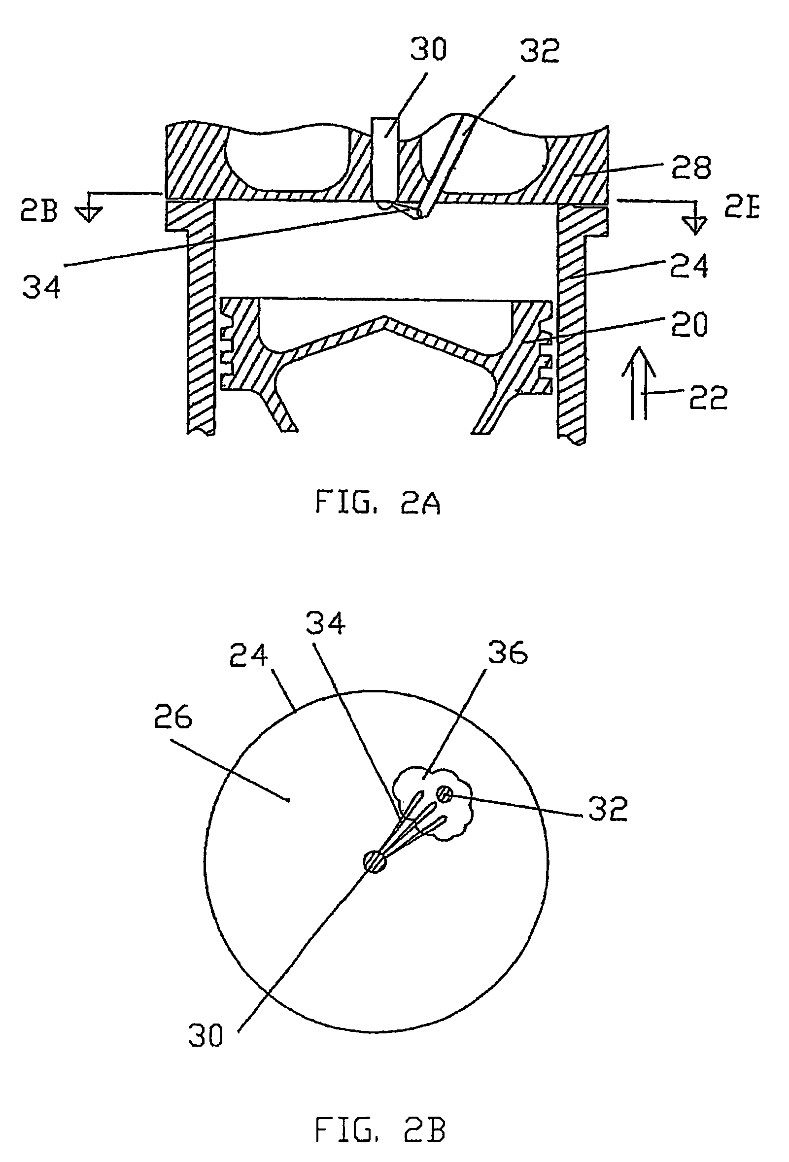
A method and apparatus create an environment within a combustion chamber of an internal combustion engine suitable for auto-ignition and combustion of a fuel that will not otherwise auto-ignite. Under high-load conditions, a pilot quantity of the fuel is injected in the combustion chamber of an internal combustion engine during the compression stroke of the piston. The quantity and timing of the fuel are chosen to heat an intake charge within the combustion chamber to a temperature at or above the auto-ignition temperature of the fuel by the time required for a main injection of the fuel to drive the piston during the power stroke. Generally, auto-ignition temperatures should be reached at or near top dead center of the piston. An injector design delivers fuel in manner carried out by the method.

Description

CROSS-REFERENCE TO RELATED APPLICATION(S)[0001]This application is a continuation of International Application No. PCT / CA2003 / 001463, having an international filing date of Oct. 2, 2003, entitled “Control Method and Apparatus for Gaseous Fuelled Internal Combustion Engine”. International Application No. PCT / CA2003 / 001463 claimed priority benefits, in turn, from Canadian Patent Application No. 2,406,137 filed Oct. 2, 2002. International Application No. PCT / CA2003 / 001463 is also hereby incorporated by reference herein in its entirety.FIELD OF THE INVENTION [0002]The present invention relates to a method and apparatus for creating a combustion event within the combustion chamber of a direct injection internal combustion engine.BACKGROUND OF THE INVENTION [0003]There are emissions benefits of operating diesel engines using natural gas. Natural gas, by way of example, is a clean burning fuel (relative to diesel). Specifically, natural gas, in general, allows engines to operate with reduc...

Claims


Application Information

Patent Timeline
Patent Type & Authority Patents(United States)
IPC IPC(8): F02B3/00F02B3/10F02B7/08F02B7/06F02M21/02F02M45/08F02M61/06F02M61/18
CPCF02B7/06F02D41/0025F02M61/06F02M61/18F02M61/182F02P19/02F02D19/061F02D19/0689F02M21/0263F02M21/0275F02D19/024F02D19/10Y02T10/36F02D41/0027F02D41/403F02M45/08F02P19/026Y02T10/32Y02T10/30F02B7/08F02M21/02
Inventor LI, GUOWEILEBASTARD, OLIVIER
Owner WESTPORT POWER
Learn More