Ultrasonic surgical blade and instrument having a gain step

a surgical blade and ultrasonic technology, applied in dental surgery, veterinary instruments, dental tools, etc., can solve the problem that the blade is not considered useful beyond its active length, and achieve the effect of increasing the active shortening the half wave length of the ultrasonic surgical blade, and increasing the active length

Active Publication Date: 2007-01-16
CILAG GMBH INT
View PDF18 Cites 477 Cited by
  • Summary
  • Abstract
  • Description
  • Claims
  • Application Information

AI Technical Summary

Benefits of technology

[0010]Several benefits and advantages are obtained from one or more of the expressions of the embodiment of the invention. Applicants found that locating a gain step having a gain greater than unity (i.e., an amplification step) further than conventionally taught from the most-distal vibration node toward the distal tip further increased the active length of the ultrasonic surgical blade even though the vibration amplitude gain was less than when conventionally locating the gain step closer to the most-distal vibration node. Applicants determined that locating the gain step further than conventionally taught from the most-distal vibration node toward the second-most-distal vibration antinode should shorten the half wave length of the ultrasonic surgical blade. Applicants also determined that such changes in active and half wave lengths of the ultrasonic surgical blade would also result from gain steps having gains less than unity (i.e., a deamplification step) but with a deamplification step causing a decrease in active length where an identically located amplification step would cause an increase in active length and with a deamplification step causing an increase in active length where an identically located amplification step would cause a decrease in active length. Being able to lengthen or shorten the active length of an ultrasonic surgical blade offers advantages for particular surgical applications, as can be appreciated by those skilled in the art.

Problems solved by technology

The blade is not considered useful beyond its active length.

Method used


Image

  • Ultrasonic surgical blade and instrument having a gain step
  • Ultrasonic surgical blade and instrument having a gain step
  • Ultrasonic surgical blade and instrument having a gain step

Examples


first embodiment

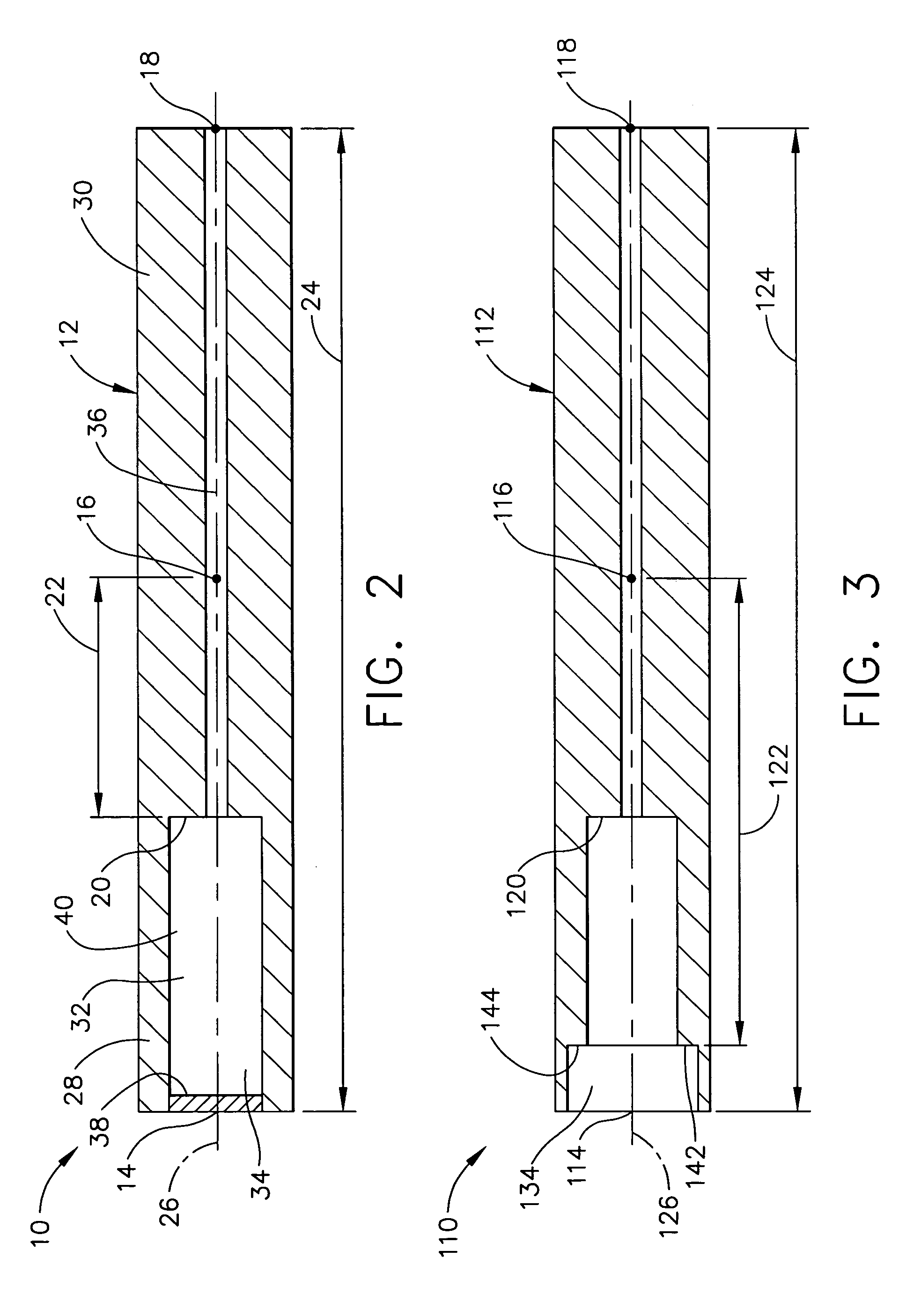
[0019]In one implementation of the first expression of FIGS. 1–2, the gain step distance 22 is between substantially 25% and substantially 45% of the distance 24 between the second-most-distal vibration antinode 18 and the distal tip 14. Those of ordinary skill in the art, employing the teachings of the invention for the location of the gain step 20, can create analytical blade models and evaluate them using a computer program to optimize design trade-offs between increased or decreased active length of the ultrasonic surgical blade and increased or decreased amplitude of the longitudinal ultrasonic vibrations for locating the gain step 20 substantially away from the most-distal vibration node 16 in the direction of the distal tip 14 or in the direction of the second-most-distal vibration antinode 18.

[0020]In one example of the first expression of the first embodiment of FIGS. 1–2, between the second-most-distal vibration antinode 18 and the distal tip 14, the maximum vibration ampl...

second embodiment

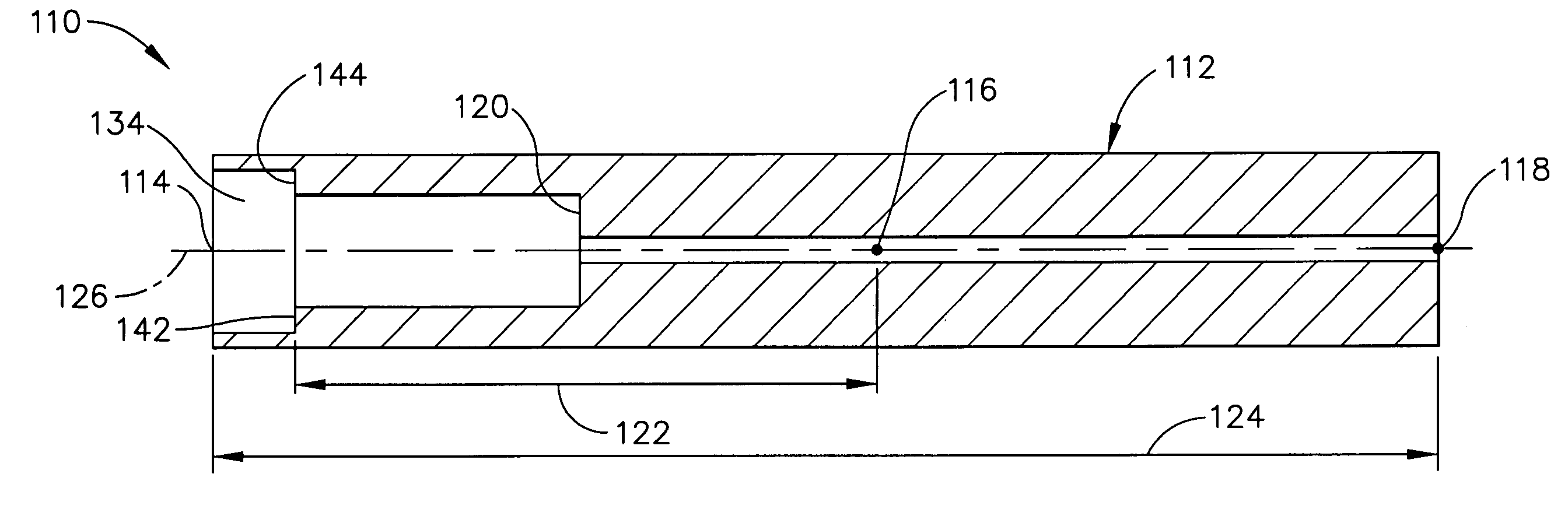
[0028]FIG. 3 illustrates the ultrasonic surgical blade 110 of the invention. In this embodiment, the ultrasonic-surgical-blade body 112 has an additional gain step 142 which is spaced-apart from the gain step 120, which is disposed between the second-most-distal vibration antinode 118 and the distal tip 114, and which is spaced apart from the most-distal vibration node 116 by a gain-step distance 122 greater than 5% of the distance 124 between the second-most-distal vibration antinode 118 and the distal tip 114. The ultrasonic-surgical-blade body 112 has a longitudinal axis 126 and a longitudinally hole 134, wherein the longitudinal hole has a shoulder 144 defining the additional gain step 142.

third embodiment

[0029]an ultrasonic surgical blade 210 is shown in FIG. 4, wherein the ultrasonic-surgical-blade body 212 consists essentially of a right-circular first geometrically-solid cylinder 288 from the gain step 220 to the distal tip 214. In this embodiment, the ultrasonic-surgical-blade body 212 consists essentially of a right-circular second geometrically-solid cylinder 230 from the gain step 220 to the second-most-distal vibration antinode 218. The diameter of the first geometrically-solid cylinder 288 is less than the diameter of the second geometrically-solid cylinder 230. It is noted that in this embodiment, the gain feature 240 is a reduced diameter from the distal tip 214 to the gain step 220 which reduces mass and which creates the first geometrically-solid cylinder 288. The gain step 220 is disposed between the second-most-distal vibration antinode 218 and the distal tip 214 and is spaced apart from the most-distal vibration node 216 by a gain-step distance 222 greater than 5% of...


PUM


Abstract

An ultrasonic surgical blade, and an instrument, having a gain step. The blade body has, in any half wave length of the ultrasonic-surgical-blade body, a first vibration antinode, a vibration node, a second vibration antinode, and a gain step. The gain step is located between the second vibration antinode and the first vibration antinode. The gain step is spaced apart from the vibration node by a gain-step distance greater than 5% of the distance between the second vibration antinode and the first vibration antinode. The instrument includes the blade, a handpiece having an ultrasonic transducer, and an ultrasonic transmission rod whose proximal end is operatively connected to the ultrasonic transducer and whose distal end activates the blade. In one option, the first vibration antinode is the distal tip, and the gain step is located between the vibration node and the distal tip, resulting in an increased active length of the blade.

Description

FIELD OF THE INVENTION[0001]The present invention relates generally to ultrasonic surgical blades and ultrasonic surgical instruments which include ultrasonic surgical blades, and more particularly to those having a gain step.BACKGROUND OF THE INVENTION[0002]Ultrasonic surgical instruments are known which include ultrasonic surgical blades. A handpiece of a known ultrasonic surgical instrument includes an ultrasonic transducer which is powered by an ultrasonic generator through a cable. An ultrasonic transmission rod of the instrument has a proximal end and a distal end, wherein the proximal end is operatively connected to the ultrasonic transducer. An ultrasonic surgical blade is activated by the distal end of the ultrasonic transmission rod. Known blade shapes include straight blades and curved blades and include blades that are symmetric and blades that are asymmetric about a longitudinal axis or about a curved centerline of the blade.[0003]A known ultrasonic surgical blade is a ...

Claims


Application Information

Patent Timeline
Patent Type & Authority Patents(United States)
IPC IPC(8): A61B17/32A61C1/07A61C3/03A61B17/22A61M1/00
CPCA61B17/320068A61B2017/22018A61B2217/005A61B2017/32008A61B2017/320072A61B2017/320089A61B17/32A61B17/22A61B18/26A61M1/00
Inventor STULEN, FOSTER B.NEUENFELDT, STEVEN K.HOUSER, KEVIN L.
Owner CILAG GMBH INT
Why Eureka
Try Eureka