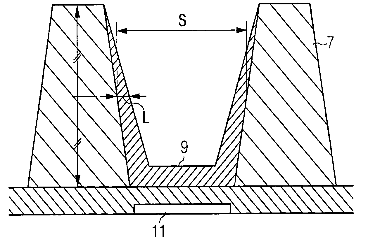
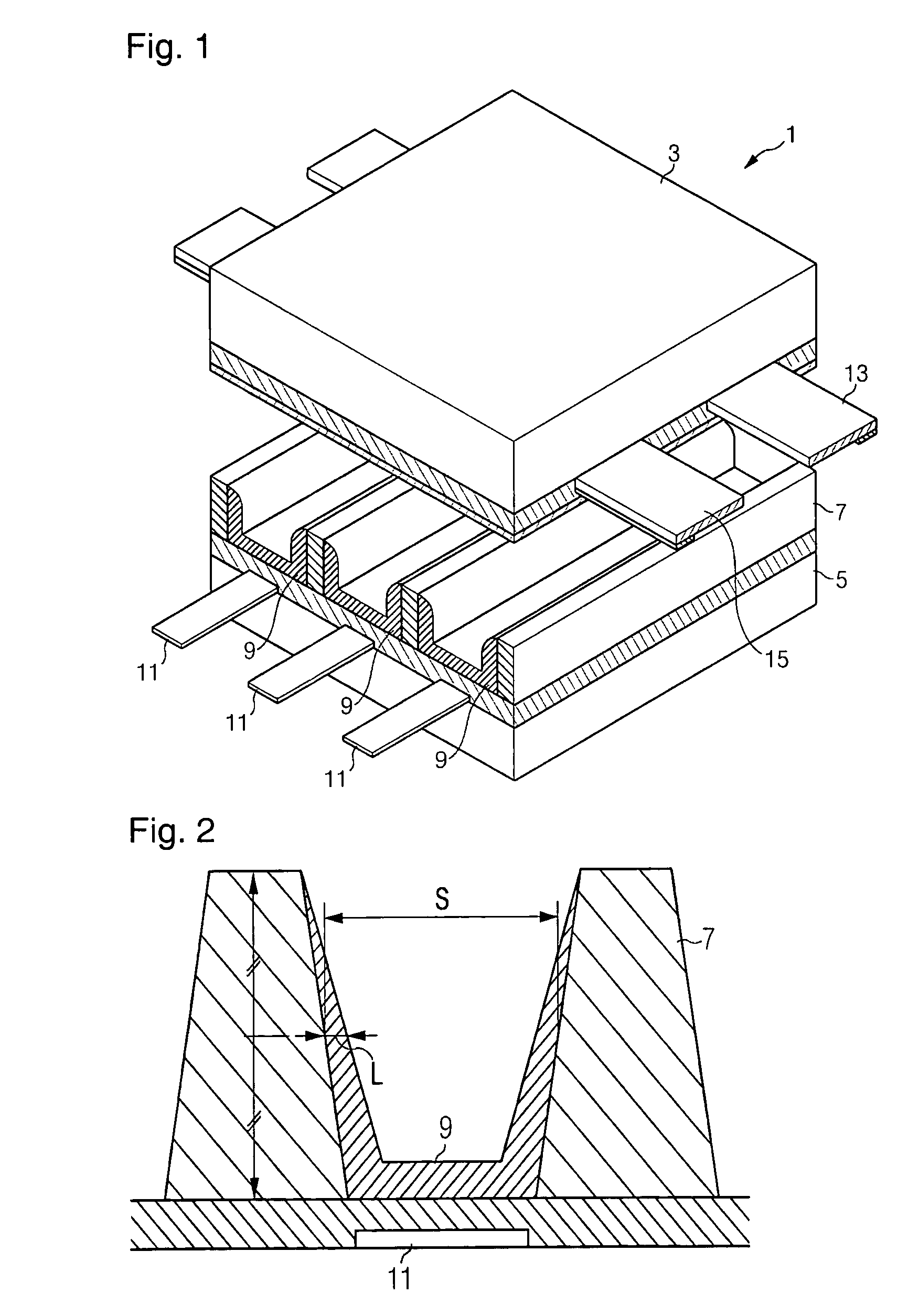
Plasma display panel with defined phosphor layer thicknesses
a technology of phosphor layer and plasma display panel, which is applied in the direction of discharge tube/lamp details, discharge tube luminescnet screens, gas-filled discharge tubes, etc., can solve the problems that the attempt to control the side thickness of the phosphor layer in order to improve the optical characteristics of the plasma display panel has not succeeded, and achieves good brightness and color purity characteristics , good optical characteristics
- Summary
- Abstract
- Description
- Claims
- Application Information
AI Technical Summary
Benefits of technology
Problems solved by technology
Method used
Image
Examples
example 1
Red Phosphor Layer
[0036](Y,Gd)BO3:Eu red phosphor was added to a binder solution in which 5.6 wt % of ethyl cellulose as a binder was dissolved in a mixed solvent of carbitol acetate and terpineol in a volume ratio of 3:7 to obtain a phosphor paste composition. The amount of the phosphor was varied to 30 wt. %, 40 wt. %, 47 wt. %, and 52 wt. %, and the phosphor paste composition was printed on the surface of a discharge cell and sintered to form a phosphor layer to provide a plasma display panel by the conventional method. Then, only the red phosphor layer was lit up, and the CIE color coordinate and the relative brightness of the red color light emitted from the plasma display panel were measured using a contact brightness meter (CA-100). The color difference was calculated using the color difference formula represented by Formula 1. The display quality was determined by examining with the naked eye whether spots appeared because of the local brightness difference upon turning on t...
example 2
Green Phosphor Layer
[0039]Green phosphor of Zn2SiO4:Mn was added to a binder solution in which 5.6 wt % of ethyl cellulose as a binder was dissolved in a mixed solvent of carbitol acetate and terpineol in a volume ratio of 3:7 to obtain a phosphor paste composition. The amount of the phosphor was varied to 30 wt. %, 40 wt. %, 50 wt. %, and 55 wt. %, and the phosphor paste composition was printed on the surface of the discharge cell and sintered to form a phosphor layer. Using the phosphor layer, a plasma display panel was obtained by the conventional method. Then, only the green phosphor layer was lit up, and the CIE color coordinate and the relative brightness of the green color light emitted from the plasma display panel were measured using the contact brightness meter (CA-100). The color difference was calculated using the color difference formula represented by Formula 1. The display quality was determined by examining with the naked eye whether spots appeared because of the loc...
example 3
Blue Phosphor Layer
[0042]Blue phosphor of BaMgAl10O17:Eu was added to a binder solution in which 5.6 wt % of ethyl cellulose as a binder was dissolved in a mixed solvent of carbitol acetate and terpineol in a volume ratio of 3:7 to obtain a phosphor paste composition. The amount of the phosphor was varied to 30 wt. %, 40 wt. %, 50 wt. %, and 65 wt. %, and the phosphor paste composition was printed on the surface of the discharge cell and sintered to form a phosphor layer. Using the phosphor layer, a plasma display panel was obtained by the conventional method. Then, only the blue phosphor layer was lit up, and the CIE color coordinate and the relative brightness of the blue color light emitted from the plasma display panel were measured using the contact brightness meter (CA-100). The color difference was calculated using the color difference formula represented by Formula 1. The display quality was determined by examining with the naked eye whether spots appeared because of the loc...
PUM
| Property | Measurement | Unit |
|---|---|---|
| color temperature | aaaaa | aaaaa |
| thickness | aaaaa | aaaaa |
| thickness | aaaaa | aaaaa |
Abstract
Description
Claims
Application Information
 - R&D
- Intellectual Property
- Life Sciences
- Materials
- Tech Scout
- Unparalleled Data Quality
- Higher Quality Content
- 60% Fewer Hallucinations
Browse by: Latest US Patents, China's latest patents, Technical Efficacy Thesaurus, Application Domain, Technology Topic, Popular Technical Reports.
© 2025 PatSnap. All rights reserved.Legal|Privacy policy|Modern Slavery Act Transparency Statement|Sitemap|About US| Contact US: help@patsnap.com


