
Antenna linear extension and retraction apparatus for a submersible device, and method of use

Inactive Publication Date: 2007-01-23
THE UNITED STATES OF AMERICA AS REPRESENTED BY THE SECRETARY OF THE NAVY
View PDF22 Cites 6 Cited by
  • Summary
  • Abstract
  • Description
  • Claims
  • Application Information

AI Technical Summary

Benefits of technology

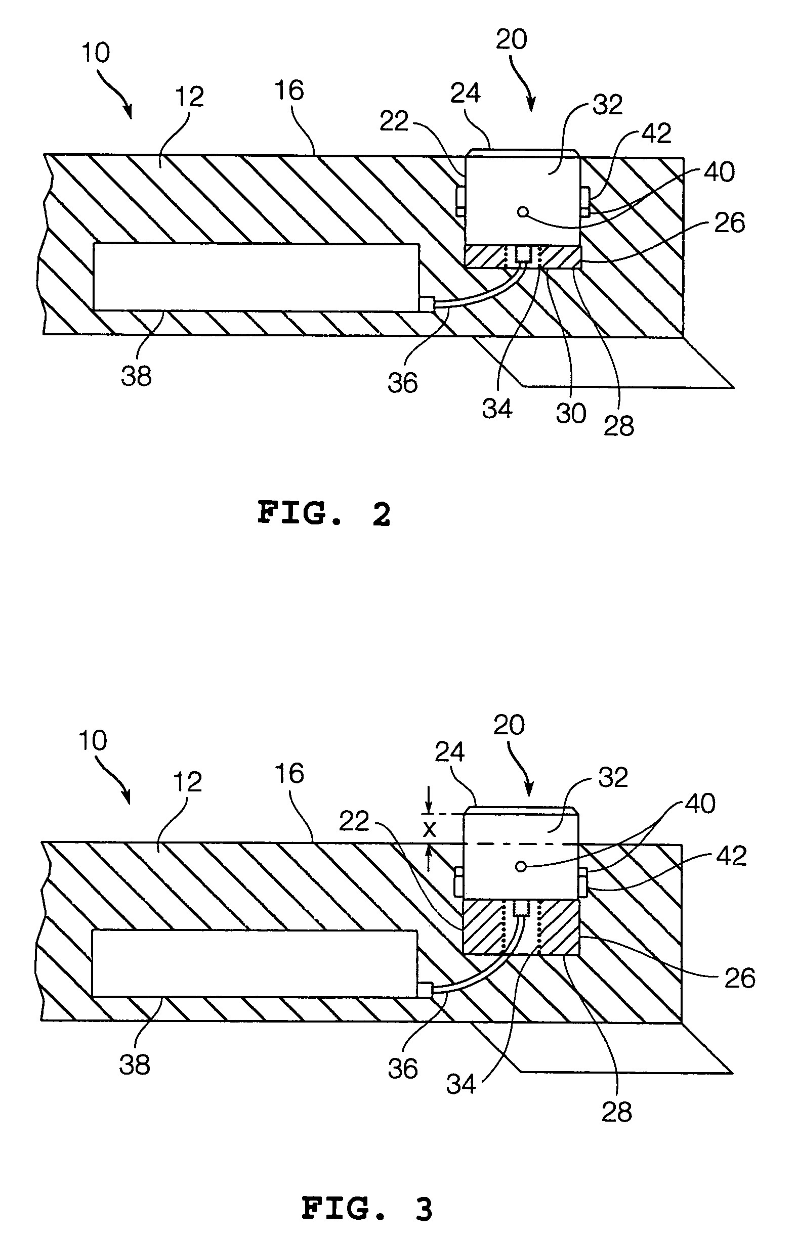
[0013]The present teachings also provide a method of retracting and extending an antenna of a submersible device. The method provides a cavity within an external surface of a body of the submersible device, provides a bladder containing a pressure-sensitive core material within the cavity, and provides an antenna in operative contact with the bladder. The method includes submerging the device at various depths to expose the antenna to various pressures that can contract and expand the bladder; thereby, causing the antenna to move between a retracted position and a deployed position.
[0014]By positioning an antenna by way of a pressure-sensitive bladder assembly as disclosed by the present teachings, the antenna linear extension and retraction apparatus and method according to various embodiments provides a lightweight, inexpensive, compact, and simple way of automatically raising and lowering an antenna from a submersible device. Moreover, the antenna linear extension and retraction apparatus and method provides improved performance by allowing the antenna to raise a great distance above the surface of the sea and by isolating the bladder from seawater.

Problems solved by technology

In the past, complicated electro-mechanical devices have been used to articulate the masts and antennas of communication buoys.
Such devices are large and heavy; thereby, requiring additional buoyancy and additional resources, such as electricity, to operate.
In addition, these devices are difficult to seal or make pressure-tolerant to prevent fouling by organic and inorganic materials.
Moreover, because communication buoys are expendable, the added cost of an electro-mechanical articulation device reduces their cost-effectiveness.
Furthermore, radio-frequency communications antennas when used with towed communication buoys suffer a degradation of performance at or near the surface of the sea.
This degradation can be attributed to the fact that a seawater-atmospheric boundary presents an imperfect environment for operating antennas.
Moreover, seawater washing onto the antenna of a communications buoy can contribute to the degradation of antenna performance.
Washing over seawater prevents the antenna from transmitting or receiving RF energy and can result in the receipt of system self-noise or erroneous information.

Method used


Image

  • Antenna linear extension and retraction apparatus for a submersible device, and method of use
  • Antenna linear extension and retraction apparatus for a submersible device, and method of use
  • Antenna linear extension and retraction apparatus for a submersible device, and method of use

Examples


Embodiment Construction

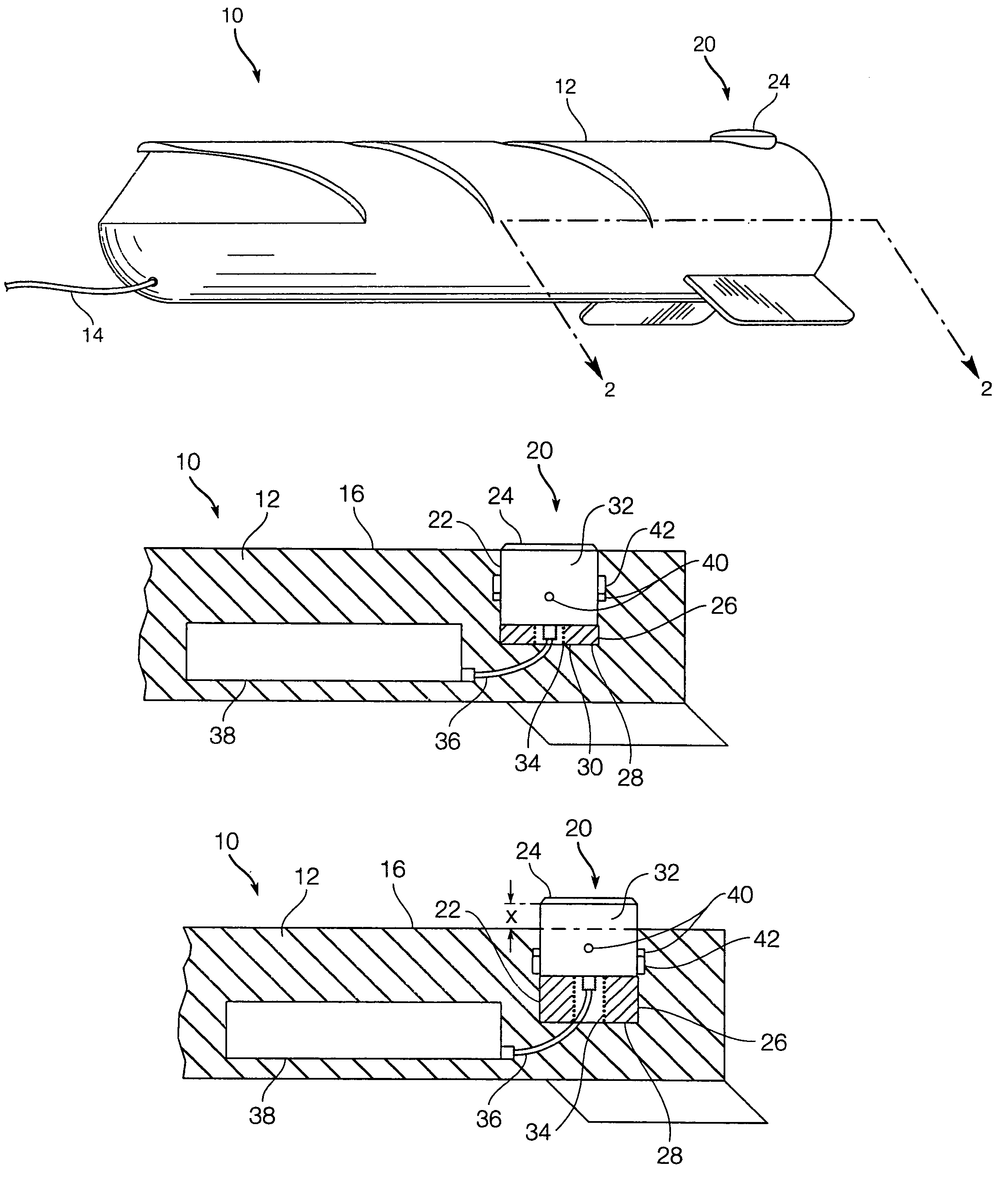
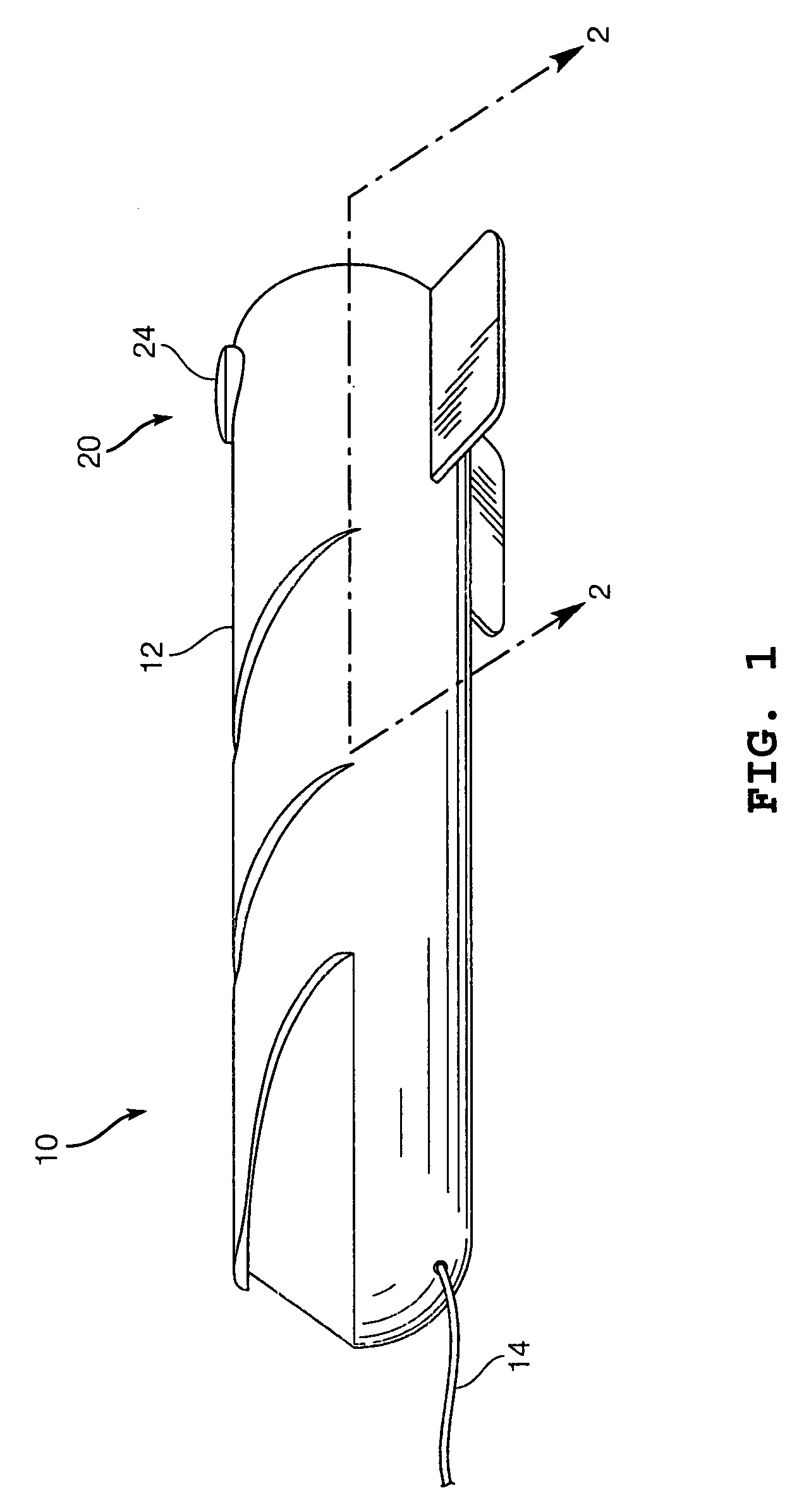
[0024]Referring to FIG. 1, a submersible device 10 is shown incorporating an antenna linear extension and retraction apparatus 20 according to various embodiments. The antenna linear extension and retraction apparatus 20 is shown in a retracted state wherein a cover or cap 24 of the antenna linear extension and retraction apparatus 20 is arranged substantially flush with an exterior surface of a main body or housing 12 of the submersible device 10. The submersible device 10 can be a communications buoy capable of communicating with and being towed by a submarine by way of a tow-cable sub-assembly 14, as shown in FIG. 1. However, it is contemplated that the submersible device 10 could encompass any type of water-based, submersible device, such as, for example, an unmanned remote or autonomous vehicle, a projectile, dingy, float, missile, torpedo, or other device that can have a communications system incorporated therein.

[0025]FIG. 2 illustrates the components of the antenna linear ex...


PUM


Abstract

An antenna linear extension and retraction apparatus and method of use for a submersible device is provided. The apparatus includes a body having a cavity formed at an external surface. A bladder containing a core material is arranged within the cavity. The core material contracts and expands the bladder depending upon a pressure that surrounds the bladder. An antenna is operatively connected with the bladder and moves between a retracted position and a deployed position as the bladder contracts and expands.

Description

STATEMENT OF GOVERNMENT INTEREST[0001]The teachings described herein may be manufactured and used by or for the Government of the United States of America for governmental purposes without the payment of any royalties thereon or therefor.BACKGROUND OF THE INVENTION[0002]1. Field of the Invention[0003]The present teachings relate to an antenna for a towed submersible device. More particularly, the present teachings relate to an apparatus and method for automatically raising and lowering an antenna from the body of a towed communications buoy.[0004]2. Description of the Prior Art[0005]As known in the art, communication buoys can be towed behind submarines by a deploying and retrieving cable. During operation and upon release from a submarine, known communication buoys are designed to rise to the surface of the sea. At the sea surface, the communication buoys deploy equipment, such as, an antenna that permits the submarine to carry-on radio communications with other, sea, land, and air...

Claims


Application Information

Patent Timeline
IPC IPC(8): H01Q1/34B63G8/38H01Q1/04H01Q1/08
CPCB63C11/02H01Q1/04H01Q3/04H01Q1/34H01Q1/081
Inventor MILLER, GRANT M.
Owner THE UNITED STATES OF AMERICA AS REPRESENTED BY THE SECRETARY OF THE NAVY
Learn More