Eureka AIR delivers breakthrough ideas for toughest innovation challenges, trusted by R&D personnel around the world.

Controlled concentration electrolysis system

a concentration control and electrolysis technology, applied in the direction of machining electric circuits, primary cell maintenance/servicing, instruments, etc., can solve the problems of not producing metal in the required particulate form, requiring expensive and cumbersome mechanical processing to put metal in the required form, and the known methods of producing metal through electrolysis are all unsatisfactory for these applications

Active Publication Date: 2007-01-23
METALLIC POWER INC
View PDF36 Cites 5 Cited by
  • Summary
  • Abstract
  • Description
  • Claims
  • Application Information

AI Technical Summary

Benefits of technology

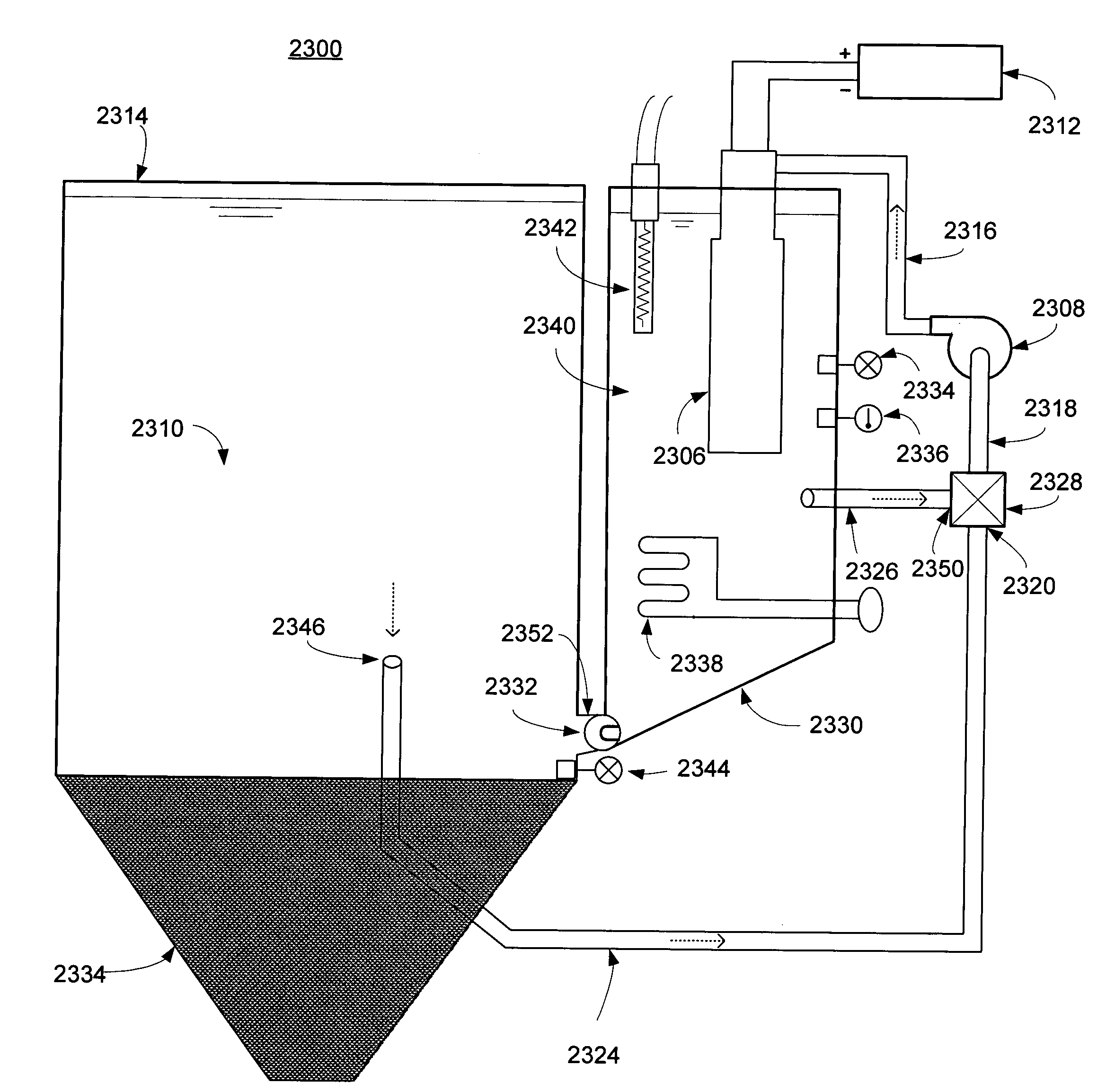
[0013]A system for producing metal particles through electrolysis is described. Particle quality is controlled by maintaining concentration of the electroreducible metal species undergoing electrolysis within a predetermined concentration range. The system comprises a first container containing a body of an electrolyte solution in which a metal is partially dissolved, a second container in fluid communication with the first container, the second container containing a second body of the solution, and a means for exchanging solution between the containers. The second container is configured with a means for electrolyzing, and a means for sensing the concentration of, the dissolved metal in the second body. During electrolysis, if the sensed concentration is within a predetermined range, the second body is circulated through the electrolyzing means, and if the sensed concentration is outside or nearly outside the range, the solution is exchanged to maintain the concentration within the range. The system also controls particle quality by sensing a temperature of the second body, and maintaining the temperature within a predetermined range responsive to the sensed temperature by exchanging, cooling, or heating the solution comprising the second body.

Problems solved by technology

Unfortunately, known methods of producing metal through electrolysis are all unsatisfactory for these applications.
Some methods, e.g., electroplating, do not produce metal in the required particulate form, and require expensive and cumbersome mechanical processing to put the metal in the required form.
This technique is not suitable for particle production because it yields dendritic zinc that requires further processing to make pellets.
Also, the curved cathodic protrusions are expensive to manufacture, and spatially inefficient.
Since the recovered metal is in the form of mossy dendrites, and cannot be easily put into the desired particulate form absent expensive and complicated mechanical processing steps, this method is likewise not suitable.
The metal is recovered by mechanically scraping the cathode which produces a powdery metal dust composed of particles so small that they are not suitable for use in a metal / air fuel cell.
However, because of the risk that metal particles will get caught in a porous separator between the anode and cathode, and cause a disastrous short between the anode and cathode, this method is unsatisfactory.
Another factor weighing against this method is the burden and expense of maintaining a supply of seed particles.
This technique is unsuitable for the applications mentioned earlier because the required mechanical forming steps are expensive, and do not permit a space-efficient and self-contained particle recovery process.

Method used


Image

  • Controlled concentration electrolysis system
  • Controlled concentration electrolysis system
  • Controlled concentration electrolysis system

Examples


second embodiment

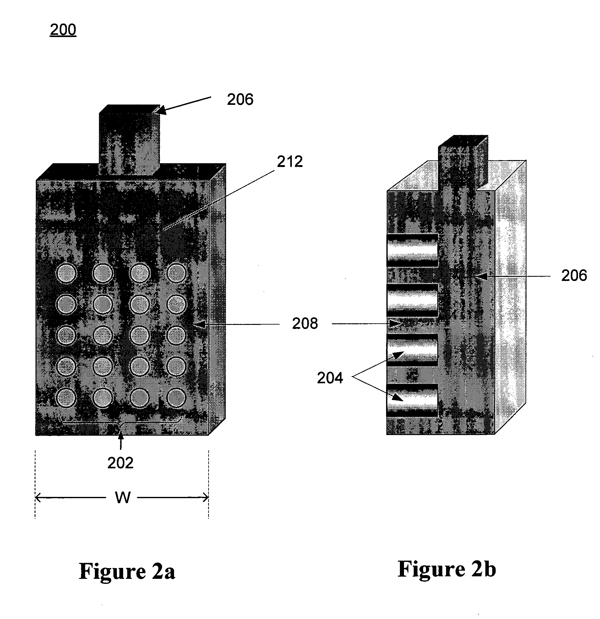
[0072]a cathode 300 is illustrated in FIGS. 3a. In this embodiment, cathode 300 is generally cylindrical in form, with a plurality of active zones 302 spaced around the outer surface 312 of the cylinder. As illustrated in FIG. 3b, rods 304 extend radially outward from conductor 306, and the ends thereof at the outer surface 312 of the cylinder form the active zones 302. Conductor 306 includes a center terminal 310 that extends axially through the cylinder, and acts as a means for external electrical connection. Insulator 308 fills the interstices between active zones 302 to achieve electrical isolation of the active zones from at each other at surface 312, and also to complete the surface 312.

[0073]FIG. 4 illustrates a second embodiment of system for metal particle production. In system 400, the electrolysis occurs inside a metal pipe 404 that functions as the anode. Metal pipe 404 has a first portion 414 and a second portion 416, and cathode 406 is situated within the second portio...

third embodiment

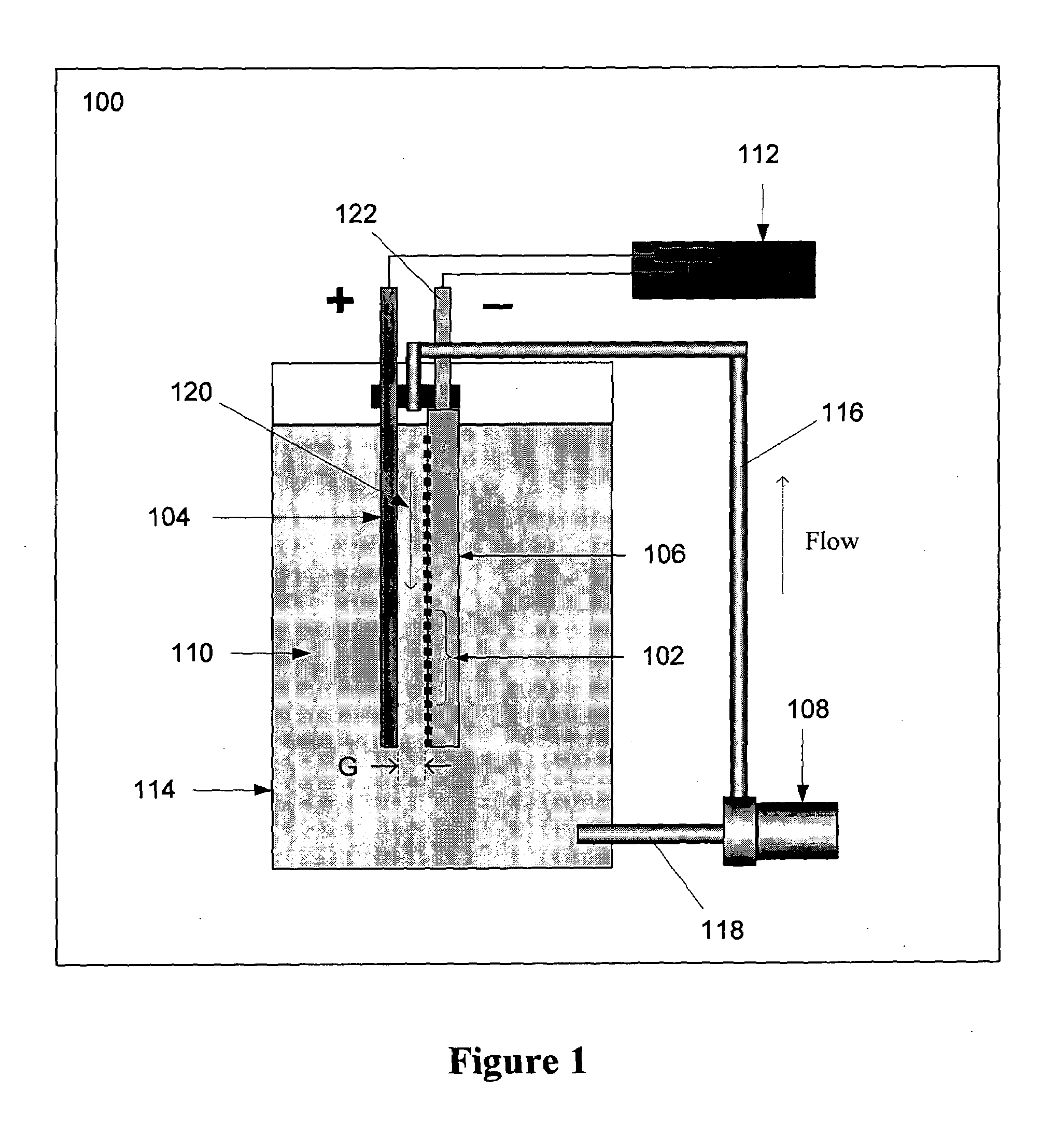
[0074]a system 500 for metal particle production is illustrated in FIG. 5. In system 500, a double-sided planar cathode 506 is situated between planar anodes 504a and 504b. In a manner similar to system 100 illustrated in FIG. 1, pump 508 circulates solution 510 into container 514 through conduit 518, and out of container 514 through conduit 520. The solution 510 is caused to flow past the surfaces 506a and 506b of cathode 506 by means respectively of flow paths 516a and 516b. Flow paths 516a and 516b in turn are created through the circulation of the solution 510 through the container 514. While solution 510 flows along flow paths 516a and 516b, power supply 512 energizes anodes 504 and cathode 506 to cause formation of metal particles on active zones 502 of the surfaces 506a and 506b of cathode 506. Once formed, the metal particles may be removed as in the previous embodiments. In this embodiment, anodes 504 are electrically connected in parallel.

fourth embodiment

[0075]a system 600 for metal particle production is illustrated in FIG. 6. System 600 comprises a plurality of the systems of FIG. 5 coupled in series. In FIG. 6, four such systems are shown, identified with numerals 624a, 624b, 624c, and 624d, but it should be appreciated that embodiments are possible in which fewer or more than four such systems are provided.

[0076]The series connection is achieved as follows: Coupler 616 connects the positive terminal of power supply 602 to the anode pair in the first system 624a. Coupler 618 connects the cathode in the first system 624a to the anode pair in the second system 624b. Similar couplers respectively connect the cathode in the second system 624b to the anode pair in the third system 624c, and the cathode in the third system to the anode pair in the fourth system 624d. The cathode in the fourth system 624d is then coupled to the negative terminal of power supply 602 through coupler 620. A dielectric material 622 may be placed between the...


PUM

PropertyMeasurementUnit
surface areaaaaaaaaaaa
diameteraaaaaaaaaa
temperatureaaaaaaaaaa

Abstract

A system for maintaining a concentration range of an electroreducible metal species undergoing electrolysis within a predetermined concentration range comprises a first container containing a body of an electrolyte solution in which a metal is partially dissolved, a second container in fluid communication with the first container, the second container containing a second body of the solution, and a means for exchanging solution between the containers. The second container is configured with a means for electrolyzing, and a means for sensing the concentration of, the dissolved metal in the second body. During electrolysis, if the sensed concentration is within a predetermined range, the second body is circulated through the electrolyzing means; if the sensed concentration is outside or nearly outside the range, the solution is exchanged to maintain the concentration within the range. Optionally, the system includes a means for sensing temperature of the second body, and a means for maintaining the temperature within a predetermined range responsive to the sensed temperature by exchanging, cooling, or heating the solution comprising the second body. A method comprising these steps is also described.

Description

[0001]This application is a continuation-in-part of U.S. patent application Ser. No. 10 / 424,539 filed Apr. 24, 2003, which is hereby incorporated by reference herein as though set forth in full.[0002]This application claims the benefit of U.S. Provisional Application No. 60 / 410,429 filed Sep. 12, 2002, U.S. Provisional Application No. 60 / 410,426 filed Sep. 12, 2002, U.S. Provisional Application No. 60 / 410,548 filed Sep. 12, 2002, U.S. Provisional Application No. 60 / 410,565 filed Sep. 12, 2002, and U.S. Provisional Application No. 60 / 410,590 filed Sep. 12, 2002, each of which is hereby fully incorporated by reference herein as though set forth in full.BACKGROUND OF THE INVENTION[0003]1. Field of the Invention[0004]This invention relates generally to production of metal particles through electrolysis, and more specifically, to a system for controlling the concentration of the electroreducible metal species to optimize the quality of metal particles produced through electrolysis.[0005]...

Claims


Application Information

Patent Timeline
Patent Type & Authority Patents(United States)
IPC IPC(8): C25C5/02C25C7/06C25D1/00C25C1/00C25C1/16H01M6/50H01M12/06
CPCC25C1/00C25C1/16H01M12/06C25C7/06H01M6/5077C25C5/02
Inventor DES JARDINS, STEPHEN R.SMEDLEY, STUART I.
Owner METALLIC POWER INC
Why Eureka
Eureka Blog
Learn More