[0012]The new automated systems and / or methods of the present invention provide efficient, reliable, cost-effective solutions to these and other as yet unnamed challenges. The present invention provides automated component processing of manually collected
whole blood. Such
whole blood can be processed into two (2) and / or three (3) component (hereafter 2 / 3 components) products, inter alia. Specifically,
whole blood may typically be separated into two component products; namely, red blood cells (also known as RBCs) and
plasma in what may be known as a two (2) component or RBC /
plasma process, and / or separated into three components; namely RBCs,
plasma and platelets (or buffy coat) in a three (3) component RBC /
platelet / plasma (or RBC / buffy coat / plasma) process. In a particular set of embodiments, a charge or unit of whole blood can be supplied to a
system of the present invention, which can then substantially automatically process that whole blood into the two or three components, and have those two or three components moved to discrete component storage containers, fully processed (or nearly fully processed; e.g. leukoreduction may be online or offline), and thence removable from the system of the present invention immediately ready for storage or use in transfusion / infusion.
[0014]The present invention is flexible to meet the needs of a
blood bank or center, with the potential to accommodate future changes in clinical, regulatory or other requirements. Protocols can also be added or changed to create a flexible platform for
blood component production. Efficiency may be provided to the user / operator through use of a single system for the production of either two or three end component products. The present invention also allows for integration of multiple processes, combining the conventionally separate processes of
pooling,
centrifugation, expression, leukoreduction and sealing of separated
blood component products now all in one
machine / instrument during one overall automated process. The present invention also provides the
advantage of providing an automated hands-off solution that is therefore simpler and less time-consuming for the operator to use. Moreover, safety is also provided whereby the present invention may be disposed as a
closed system safe for the operators and ultimately also for the patients receiving the high quality end products produced hereby. Quality may be highly controlled by the automated systems and methods hereof so that the highest quality standards can be achieved and the highest rates of consistency in component processing can be delivered which lead to consistent high quality outcomes. Such quality outcomes may include achieving greater yields than conventional manual preparation methods. The present invention may further provide control in using one or more eyes or optical sensor(s) in the process and such integral monitoring provides accurate, automated control of any or all processes.
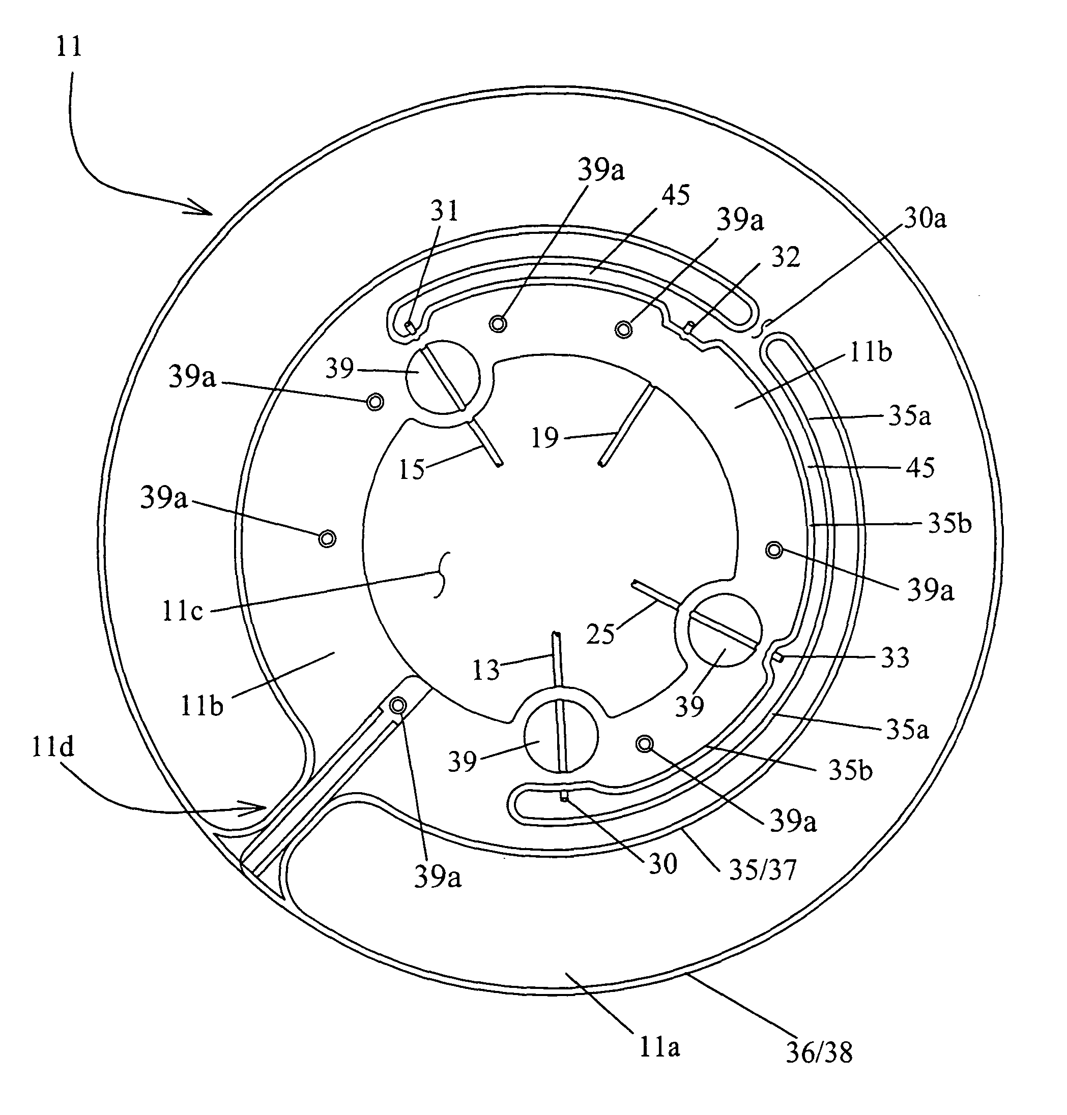
[0015]An aspect of the present invention is to provide a method and / or system that solves the above-mentioned problems and affords effective and timely preparation of blood components of high purity. This may be achieved using a
centrifuge and a set of containers as parts of the system adapted each to the other. The set of containers may preferably include a substantially flat and / or conical, round or ring-like separation container. A set of containers according to the invention may further include at least one component container connected by a tube to an outlet from the ring-like separation container. One or more of the container(s) in the set of containers may be made of one or more flexible materials and / or thus be like bags used in otherwise conventional
blood processing. The separation container or bag set may further include various features such as tubing line positioning which may be adapted for operative relationship(s) with one or more corresponding clamp or pinch valves optionally mounted in and / or on the separation rotor of the centrifuge.
[0016]A loading device may also be included in one or more embodiments for receiving and holding the container or bag set and assist or improve operator handling during
insertion and / or loading of the container or bag set in, as well as providing better maneuverability of the bag set outside, the centrifuge system. Such a loading device may be
single use or may be reused and thus applied to use with a new separation container and bag set after transfer or removal therefrom of the previously finished component products; plasma, red blood cells and / or platelets (or buffy coats).
[0017]In use, the method and / or system may involve control over the centrifuge rotational characteristics, such as speed, as well as control over the flows in and / or out of respective containers using, for example, one or more optical or pressure sensors and controlled valves. Moreover, the transfer of the separated component products, e.g., plasma, platelets (or buffy coat) and / or red blood cells to their respective
secondary component containers can be carried out inside the centrifuge system, either after, and / or during the centrifuging
separation process, i.e., during continued centrifuge rotation but preferably after a certain minimal separation has been achieved. Note, in most embodiments herein, the displacement of any separated components to an associated container may be made to preferably take place during continued centrifugal rotation while the fluid
layers thus remain subjected to the centrifugal forces. In this type of process as described generally herein, one charge or unit of blood will usually (though not necessarily) be processed in each centrifugation, which means that a short
process time in the centrifuge would be highly desirable in routine preparation of blood components therefrom.

