DLC film, DLC-coated plastic container, and method and apparatus for manufacturing DLC-coated plastic container

a technology of dlc film and plastic containers, which is applied in the direction of coatings, chemical vapor deposition coatings, plasma techniques, etc., can solve the problems of unsuitable plastic containers for drinks, plastic containers are often limited in their application, and drink will go flat, so as to achieve the effect of reducing the oxygen transmission rate preventing the loss of transparency of containers, and improving the productivity of dlc film-coated plastic containers

Inactive Publication Date: 2007-01-23
MITSUBISHI SHOJI PLASTICS +2
View PDF26 Cites 24 Cited by
  • Summary
  • Abstract
  • Description
  • Claims
  • Application Information

AI Technical Summary

Benefits of technology

[0022]The object of the invention is also attained by providing a DLC film to be formed on the surface of a plastic molding and having a thickness of from 50 to 400 Å, a hydrogen content of 39 to 52 hydrogen atomic % and a density of from 1.2 to 1.6 g / cm3. In this aspect of the invention, the DLC film has a thickness of from 50 to 400 Å. In this, therefore, the oxygen transmission rate through the DLC film is effectively reduced, and the transparency of the DLC film-coated plastic molding is well prevented from being reduced owing to the discoloration of the DLC film. In addition, since the DLC film is prevented from being cracked owing to compression stress applied thereto, the oxygen barrier properties of the DLC film-coated plastic molding are well prevented from being degraded. Further, since the time for vapor deposition to form the DLC film is shortened, the productivity of the DLC film-coated plastic molding is improved.
[0024]The object of the invention is also attained by providing a plastic container with its inner surface coated with DLC film formed thereon, in which the DLC film has a thickness of 50 to 400 Å, a hydrogen content of 39 to 50 hydrogen atomic % and a density of from 1.2 to 1.6 g / cm3. In this aspect of the invention, the DLC film has a thickness of from 50 to 400 Å. In this, therefore, the oxygen transmission rate through the DLC film-coated plastic container is effectively reduced, and the transparency of the container is well prevented from being reduced owing to the discoloration of the DLC film. In addition, since the DLC film is prevented from being cracked owing to compression stress applied thereto, the oxygen barrier properties of the DLC film-coated plastic container are well prevented from being degraded. Further, since the time for vapor deposition to form the DLC film is shortened, the productivity of the DLC film-coated plastic container is improved.

Problems solved by technology

Therefore, as compared with glass containers, plastic containers are often limited for their applications and forms.
In addition, carbon dioxide gas in the packed carbonated drinks will pass through the plastic containers outside them, and the drinks will go flat.
Therefore, plastic containers are unsuitable to drinks that must not be oxidized, and to carbonated drinks.
As a result, the composition of the flavoring ingredients of the packed drinks will be unbalanced, and the quality of the drinks will become poor.
For these reasons, plastic containers are unsuitable to drinks with flavoring ingredients.
The recent tendency in the art is toward recycling natural resources, for which the problem is how to collect and recover used containers.
Accordingly, using plastics for returnable containers is limited, being different from the case of using glass for returnable containers.

Method used


Image

  • DLC film, DLC-coated plastic container, and method and apparatus for manufacturing DLC-coated plastic container
  • DLC film, DLC-coated plastic container, and method and apparatus for manufacturing DLC-coated plastic container
  • DLC film, DLC-coated plastic container, and method and apparatus for manufacturing DLC-coated plastic container

Examples


example 1

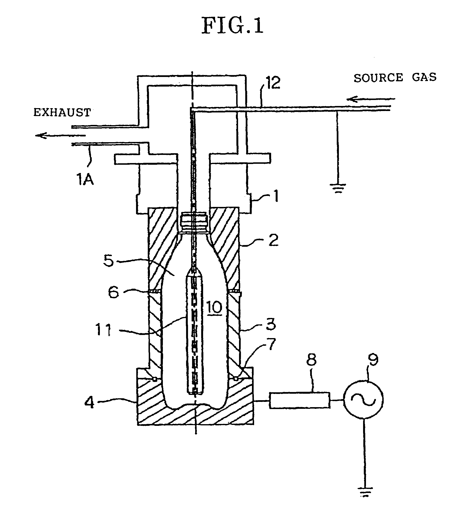
[0054]This is to demonstrate the formation of a DLC film on the inner surface of 500 ml PET (polyethylene terephthalate) bottles by the use of the apparatus mentioned above under different conditions mentioned below. The coated bottles were tested for their properties, and the data obtained are given below.

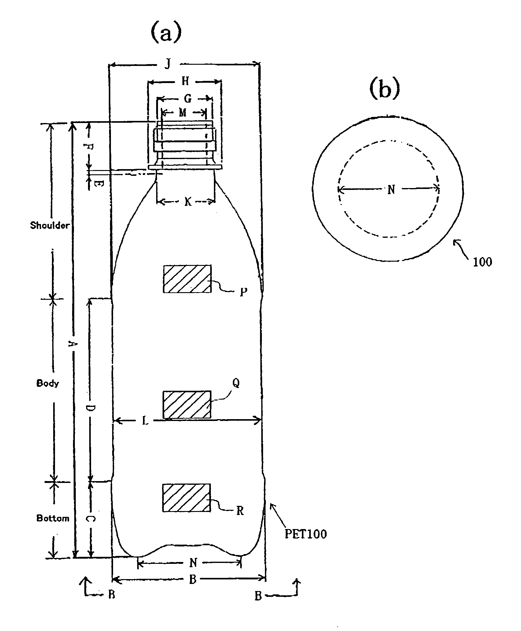
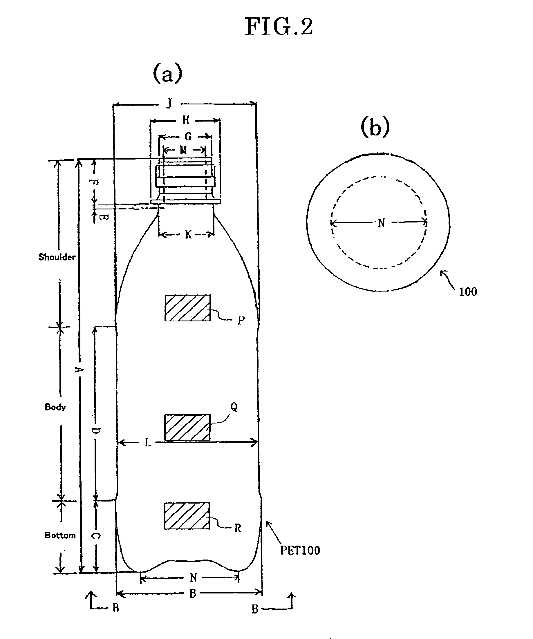
[0055]Table 1 shows the condition for plasma CVD employed herein, and the dimension and the shape of the PET bottles and others coated herein. Table 2 shows the methods for testing and evaluating the bottles of which the inner surface was coated with a DLC film. Table 3 shows the film-forming conditions for which toluene was used as the raw material gas, and the test data of the coated bottles. Table 4 shows the film-forming conditions for which acetylene was used as the raw material gas, and the test data of the coated bottles.

[0056]

TABLE 1ACondition for Plasma CVD(1)High-frequency Power: 500 to 1500 W.(2)Vacuum Degree: 0.01 to 0.07 Torr.(3)Gas Flow Rate: 1.7 to 31 cc / min.(4)Raw ...

example 2

[0065]This is to demonstrate the formation of a thinner DLC film on the inner surface of 500 ml PET (polyethylene terephthalate) bottles than in Example 1, under different film-forming conditions as in Table 5 below, for which is used the apparatus mentioned above. The coated bottles were tested and the test data obtained are given in Table 5.

[0066]In Example 2, the period for exposure to plasma is relatively shortened, and therefore the DLC film formed is thin.

[0067]

TABLE 5OxygenPeriod forFilmTransmissionExposure toThicknessRateTest No.Plasma (sec)(Å)(ml / day / bottle)1000.0332250–750.00834 90–1600.00746150–2300.004–0.00658200–3000.004610250–3800.003–0.004

[0068]The condition for exposure to plasma in Tests Nos. 1 to 6 is as follows: Acetylene was used as the raw material gas. For discharging, a high-frequency power was applied to only the bottom electrode 4. Precisely, the shoulder electrode 2, the body electrode 3 and the bottom electrode 4 were electrically insulated from each other...

example 3

[0075]A DLC film was formed on the inner surface of 500 ml PET bottles by the use of the apparatus mentioned above. The details of the film-forming condition employed herein are given in Table 6. The DLC film-coated bottles were tested and the test data are in Table 6. With reference to the data in Table 6, the coated bottles are discussed in point of the density of the DLC film.

[0076]

TABLE 6OxygenTransmissionDischargingHigh-FrequencyThicknessVolumeWeightDensityRateTest No.MethodPower AppliedPart of BottleÅ10−3 cm3mgg / cm3ml / day / bottle7whole 800 Wshoulder3180.3870.7271.88—body2130.3930.5781.47bottom2570.2490.3361.358whole1200 Wshoulder4320.5260.7371.40—body2320.4290.6271.46bottom2920.2830.3931.399bottom 800 Wshoulder2770.3770.7882.090.003body2190.4050.4931.22bottom2150.2090.3341.5910 bottom1200 Wshoulder3010.3670.8472.300.003body1970.3640.7302.01bottom3040.2950.4371.48

[0077]The condition for exposure to plasma in Tests Nos. 7 to 10 is as follows: Acetylene was used as the raw materia...


PUM

PropertyMeasurementUnit
densityaaaaaaaaaa
densityaaaaaaaaaa
frequencyaaaaaaaaaa

Abstract

Disclosed is an apparatus for producing DLC film-coated plastic containers, which comprises an outer electrode unit disposed outside a plastic container, an inner electrode disposed inside the plastic container, a duct through which a raw material gas of a carbon source is fed into the plastic container having been degassed, and a high-frequency oscillator for applying a voltage between the outer electrode unit and the inner electrode with a carbon source gas being fed into the container, thereby to generate plasma to form a DLC film on the inner surface of the plastic container. In the apparatus, the outer electrode unit comprises a bottom electrode disposed along the bottom of the plastic container, and a body electrode disposed along the body of the plastic container, and the upper edge of the bottom electrode is positioned below the center between the top and the bottom of the plastic container. DLC films having good oxygen barrier properties, and DLC film-coated plastic containers suitable to oxygen-sensitive drinks and to sparkling drinks are produced by the use of the apparatus. Also disclosed is a method for producing a DLC film on the inner surface of a plastic container by the use of the apparatus.

Description

BACKGROUND OF THE INVENTION[0001]1. Field of the Invention[0002]The present invention relates to DLC film-coated plastic containers suitable to beers, sparkling wines, wines, high-fruit drinks and others that are sensitive to oxygen.[0003]2. Description of the Related Art[0004]In general, plastic containers are easy to form, lightweight and inexpensive, and are therefore widely used as packing containers in various fields of edibles, drinks, medicines, etc.[0005]As well known, however, plastics have the property of passing low-molecular gases such as oxygen, carbon dioxide and others therethrough, and the property of absorbing or adsorbing low-molecular organic compounds. Therefore, as compared with glass containers, plastic containers are often limited for their applications and forms.[0006]For example, in case where plastic containers are used for packing carbonated drinks such as beers and others, or wines, oxygen will penetrate them to time-dependently oxidize the drinks packed ...

Claims


Application Information

Patent Timeline
Patent Type & Authority Patents(United States)
IPC IPC(8): B05D7/22C23C16/507H05H1/46C23C16/26C23C16/27C23C16/04
CPCC23C16/26C23C16/045
Inventor MORI, SHIGEKIYAMASHITA, YUUJIKAGE, TSUYOSHI
Owner MITSUBISHI SHOJI PLASTICS
Why Eureka
Try Eureka