Image input/output system, image input/output control device, and control method therefor using device information indicating active execution of data communication or passive execution of data communication

a control device and image input technology, applied in the field of image input/output system, image input/output control device, and control method therefor, can solve the problems of device information not being able to be actually combined, devices cannot be actually combined, devices cannot be combined,

Inactive Publication Date: 2007-01-23
CANON KK
View PDF4 Cites 28 Cited by
  • Summary
  • Abstract
  • Description
  • Claims
  • Application Information

AI Technical Summary

Benefits of technology

[0012]The present invention has been made to solve the above problems, and has as its first object to provide a multi-functional system which easily constitutes a number of virtual input and output devices

Problems solved by technology

However, the combinations of combinable devices are limited to a combination of an active input device and a passive output device and a combinations of a passive input device and an active output device.
More specifically, in attempting to combine, e.g., a push-type scanner with a pull-type printer, these devices cannot be actually combined because both the devices are designed to actively start data transfer, and the transfer control directions do not match.
Conversely, in attempting to combine a conventional passive scanner with a passive printer, these devices cannot be actually combined because both the devices are designed to wait for a transfer instruction from the other party of data transfer, and the transfer control directions do not match.
That is, many kinds of input and output devices connected to the network cannot be effectively

Method used


Image

  • Image input/output system, image input/output control device, and control method therefor using device information indicating active execution of data communication or passive execution of data communication
  • Image input/output system, image input/output control device, and control method therefor using device information indicating active execution of data communication or passive execution of data communication
  • Image input/output system, image input/output control device, and control method therefor using device information indicating active execution of data communication or passive execution of data communication

Examples


first embodiment

[First Embodiment]

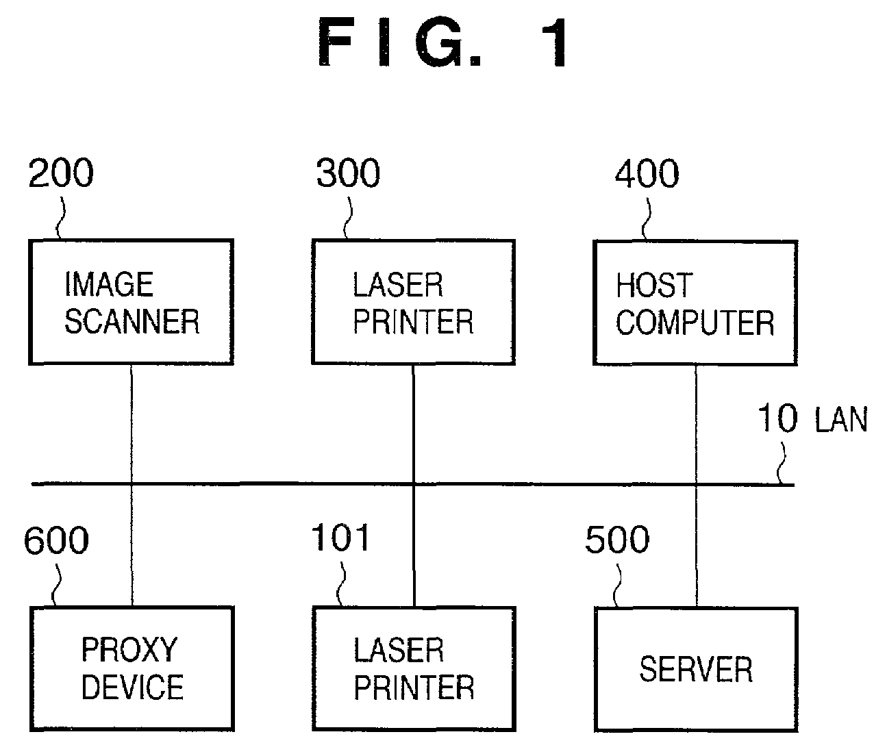
[0128]FIG. 1 is a block diagram showing the arrangement of a network including one image scanner and two laser printers. Each of the image scanner and laser printers has a network board to connect itself to the network. Referring to FIG. 1, a laser printer 101 is a laser beam printer having the same arrangement as that of a laser printer 300. One proxy device is also connected.

[0129]The network board of each device is connected to a local area network (LAN) 10 through a LAN interface such as a 10Base2 as an Ethernet interface having a coaxial connector or 10Base-T having RJ45.

[0130]A plurality of host computers including a host computer 400 are also connected to the LAN. These host computers can communicate with the network board of each device under the control of the network operating system.

[0131]A server computer 500 is connected to the LAN 10. The server computer 500 can communicate with the host computer or the network board of each device under the control o...

second embodiment

[Second Embodiment]

[0286]The second embodiment of the present invention will be described below. The same reference numerals as in the first embodiment denote the same components in the second embodiment, and a detailed description thereof will be omitted.

[0287]The network system of this embodiment has the arrangement shown in FIG. 1. In this embodiment, a printer 300 is a printer having a so-called pull printer function as an active output device. A scanner 200 is a so-called push scanner as an active input device. This system combines these devices to implement a virtual copying machine distributed to the network.

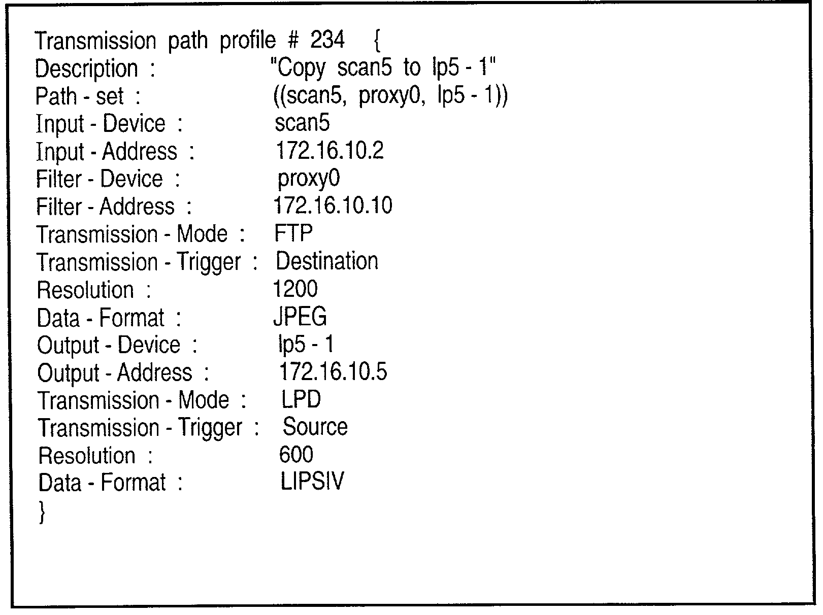
[0288]FIG. 21 is a view showing device profile information according to the second embodiment, which describes the device information of the image scanner.

[0289]Device-Type represents the type of device, i.e., whether the device is an input device or output device, or a proxy device (filter) for performing transfer. The device type is described in more detail after a slas...

third embodiment

[Third Embodiment]

[0351]The third embodiment of the present invention will be described below in detail with reference to the accompanying drawings. The network configuration and the arrangement of each device in the network are the same as in FIGS. 1 to 6 of the first embodiment, and a detailed description thereof will be omitted. In this embodiment, however, unlike the virtual input / output device of the first or second embodiment in which active input and output devices or passive input and output devices are combined, input and output devices one of which is an active device and the other is a passive device are combined. Hence, the device profiles of the combined devices are different from the first and second embodiments.

[0352]A device profile which describes the device attribute of each device and processing of causing each device to announce through the network in this embodiment will be described.

[0353]FIG. 21 is a view showing device profile information according to the thi...


PUM


Abstract

The present invention easily implements a virtual copying machine by connecting a scanner and printer on a network. When a passive scanner and passive printer are connected through a proxy device, the device profiles of the devices are collected to generate a transfer path profile. By referring to the transfer path profile, the proxy device issues an input request to the scanner to cause it read an image, receives the image data, issues an output request to the printer, and transfers the data received from the scanner to the printer to cause it to print the data.

Description

FIELD OF THE INVENTION[0001]The present invention relates to an image input / output system constituted by input and output devices connected through, e.g., a network, an image input / output control device, and a control method therefor.BACKGROUND OF THE INVENTION[0002]Conventionally, a digitized input device such as an image scanner, digital camera, facsimile receiver, or image file system (reading section) is generally connected to a computer and executes input processing under the control of the computer. That is, the input device plays a passive role that data is extracted by the connected computer. In recent years, push-type input devices have also been developed, in which the input device side actively executes the input processing and sends data to a data sending destination.[0003]Conventionally, a digitized output device such as a printer, facsimile transmitter, or image file system (writing section) is generally connected to a computer and executes output processing under the ...

Claims


Application Information

Patent Timeline
IPC IPC(8): G06F15/00G06K1/00B41J29/38G06F3/12G06F13/00H04N1/00H04N1/387
CPCH04N1/00127H04N1/00278H04N2201/0015H04N2201/0082H04N2201/0075H04N2201/0081H04N2201/0034
Inventor YAMAMOTO, MASAHITO
Owner CANON KK
Why Eureka
Try Eureka