

Thermal and power management for computer systems
- Summary
- Abstract
- Description
- Claims
- Application Information
AI Technical Summary
Benefits of technology
Problems solved by technology
Method used
Image

Examples
first embodiment
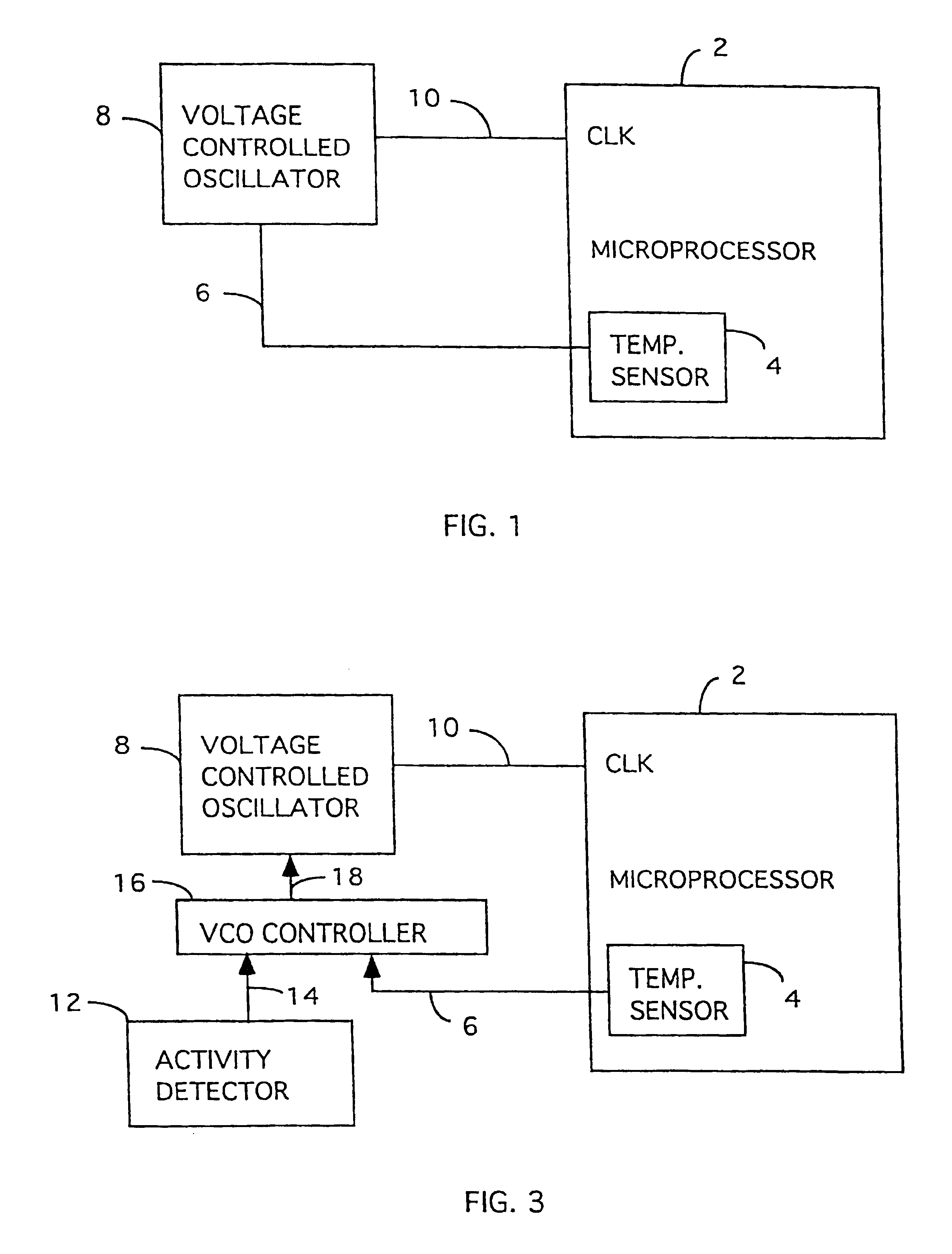
[0035]FIG. 1 is a block diagram of the invention. In this embodiment, a microprocessor 2 has a temperature sensor 4 which is integral with the microprocessor 2. The temperature sensor 4 is either integrated within the Very Large Scale Integration (VLSI) design of the microprocessor 2 or placed in contact with the housing or package thereof. In either case, the temperature sensor 4 is thermally coupled with the microprocessor 2. Because the temperature sensor 4 is integral or thermally coupled with the microprocessor 2, the temperature sensor 4 is very responsive to the temperature changes of the microprocessor2. The temperature sensor 4 produces a temperature signal 6. Temperature sensing circuitry is well known and therefore not further described.
[0036]The temperature signal 6 is supplied to a voltage-controlled oscillator (VCO) 8. The VCO 8 produces a clock signal 10 which is supplied to a clock input of the microprocessor 2. The VCO 8 operates to produce different frequencies for...
second embodiment
[0041]The second embodiment is particularly advantageous for portable computing devices because it conserves battery life by using a sleep clock when no processing is needed. However, even in the case of prolonged processing, the embodiment prevents overheating.
third embodiment
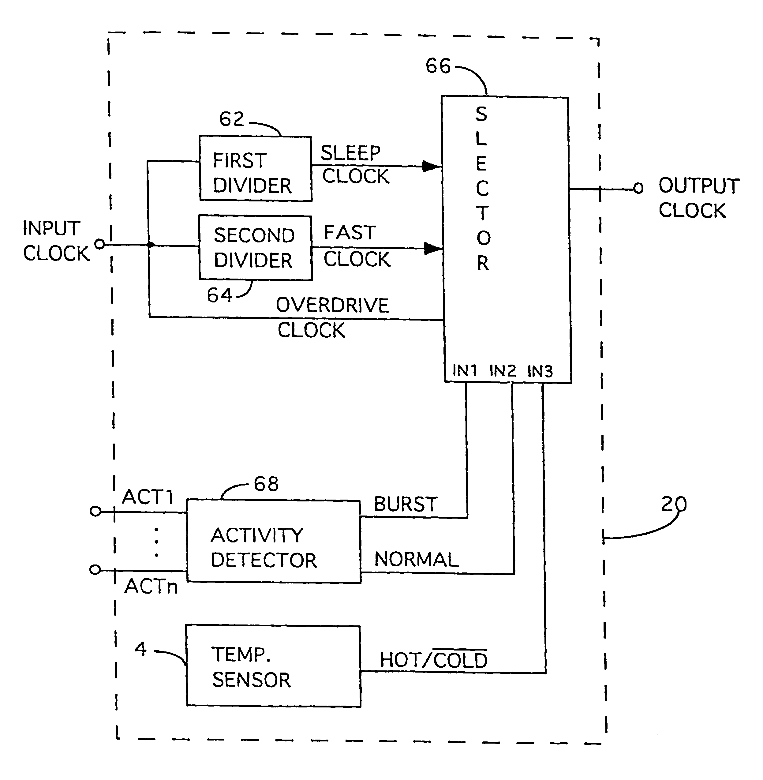
[0042]FIG. 4 is a block diagram of the invention. In this embodiment, the microprocessor 2 includes a clock regulation unit 20 which controls the frequency of the clock used by the microprocessor 2 based on chip temperature of the microprocessor 2. Preferably, the clock regulation unit 20 is integrated with circuitry of the microprocessor 2. Alternatively, the clock regulation unit 20 can be separate from the circuitry of the microprocessor 2 but nevertheless coupled thereto.
[0043]The clock regulation unit 20 receives an input clock from an oscillator 22 and produces an output clock which is used by the microprocessor 2. The clock regulation unit 20 includes a temperature sensor 4, a divider 24, a first AND gate 26, a second AND gate 28, an inverter 30 and an OR gate 32. The temperature sensor 4 is as previously described. The divider 24 divides the input clock (fast clock) from the oscillator 22 to produce a sleep (or slow) clock. For example, if the oscillator 22 is a 100 MHz fixe...
PUM
 Abstract
Description
Claims
Application Information