Exhaust-steam pipeline for a steam power plant

a technology for exhaust steam and steam power plants, which is applied in the direction of process and machine control, lighting and heating apparatus, instruments, etc., can solve the problems of flow loss, inability to reduce the pressure drop beyond a certain level, and loss typically experienced in the area, so as to reduce the height of the platform, facilitate the operation of the plant, and facilitate the effect of operation

Active Publication Date: 2007-01-30
ENEXIO ACC GMBH
View PDF20 Cites 24 Cited by
  • Summary
  • Abstract
  • Description
  • Claims
  • Application Information

AI Technical Summary

Benefits of technology

[0011]The present invention resolves prior art problems by providing a substantial direct link between the connection of the main steam line at the lower end and several connections of the branch lines to the distribution pipes at a higher level. The upward inclination of the main steam line has the advantage that the individual branch lines, although of different lengths, can be designed shorter overall compared to horizontal main steam lines. As a consequence, the length of the flow path is reduced overall.
[0023]The inclined construction of the main steam line results in an improved supply of cooling air underneath the condenser elements, thereby enabling, depending on the arrangement, the provision of a lower platform height and thus a reduction of the steel construction costs. Moreover, accessibility to the plant is enhanced as the area underneath the main steam line is clear.

Problems solved by technology

A drawback of this construction is the inability to decrease the pressure drop beyond a certain level.
Losses are typically experienced in the area of the connection zones, when the flow of exhaust steam is deflected.
These flow losses are in addition to the pressure drops as encountered along the pipeline.
This complicates the installation.
The overall length of the pipeline is relatively long so that substantial tonnage needs to be transported which in turn also complicates the assembly.
Also, accessibility is impeded and requires oftentimes covering of very long distances as any direct path is blocked by the bottom-proximal main steam line 2.
Thus, this great mass no only complicates the assembly but poses also a problem in connection with earthquakes.
This involves, however, the risk that in the event of vertical shocks caused by an earthquake the spring supports are incapable to absorb the relatively great mass of the main steam line and the guide vane elbow.

Method used


Image

  • Exhaust-steam pipeline for a steam power plant
  • Exhaust-steam pipeline for a steam power plant
  • Exhaust-steam pipeline for a steam power plant

Examples


Embodiment Construction

[0035]Throughout all the Figures, same or corresponding elements are generally indicated by same reference numerals. These depicted embodiments are to be understood as illustrative of the invention and not as limiting in any way. It should also be understood that the drawings are not necessarily to scale and that the embodiments are sometimes illustrated by graphic symbols, phantom lines, diagrammatic representations and fragmentary views. In certain instances, details which are not necessary for an understanding of the present invention or which render other details difficult to perceive may have been omitted.

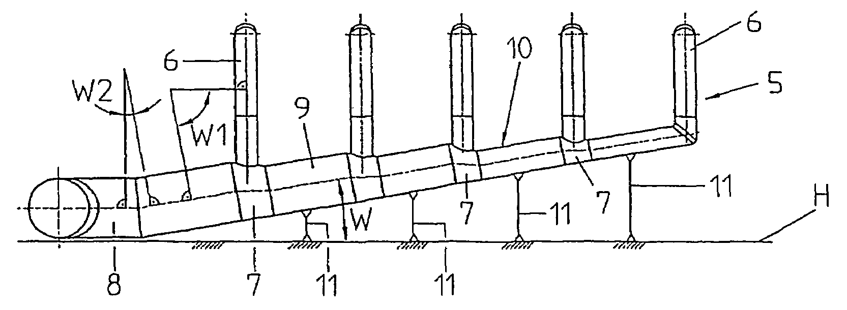
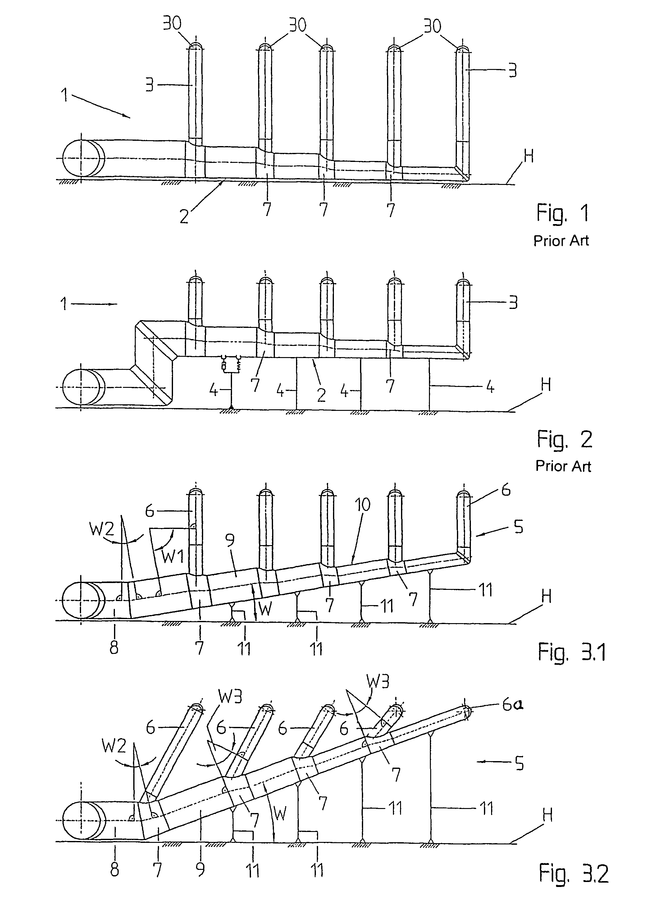
[0036]Turning now to the drawing, and in particular to FIG. 3.1, there is shown a schematic illustration of one embodiment of an exhaust steam pipeline according to the present invention, generally designated by reference numeral 5 and including a main steam line 10 which carries exhaust steam and extends slantingly upwards at an angle W in relation to the horizontal H from a ...


PUM


Abstract

An exhaust steam pipeline for steam power plants includes a main steam line and at least two branch lines which are fluidly connected to respective condenser elements of the steam power plant and branch off from the main steam line at connection zones in spaced-apart relationship. The main steam line has a cross section, which decreases following each of the connection zones, and is constructed to ascend at an angle to a horizontal in flow direction of the exhaust steam.

Description

CROSS-REFERENCES TO RELATED APPLICATIONS[0001]This application is a continuation of prior filed copending PCT International application no. PCT / DE2004,001417, filed Jul. 2, 2004, which designated the United States and on which priority is claimed under 35 U.S.C. §120, and which claims the priority of German Patent Application, Serial No. 103 30 659.5, filed Jul. 8, 2003, pursuant to 35 U.S.C. 119(a)–(d).BACKGROUND OF THE INVENTION[0002]The present invention relates, in general, to an exhaust-steam pipeline for a steam power plant.[0003]An exhaust-steam pipeline for a steam power plant, in particular steam turbine, is intended to carry exhaust steam from the outlet of the steam turbine via a main steam line to branch lines by which the exhaust steam is directed to individual condenser elements. This process is executed mainly under vacuum conditions. The exhaust-steam pipeline for an air-cooled condenser normally has a diameter between 1 m and 10 m. The presence of local flow losses ...

Claims


Application Information

Patent Timeline
Patent Type & Authority Patents(United States)
IPC IPC(8): F02B9/02F28B1/06F28B9/02G05D7/00
CPCF28B1/06F28B9/02Y10S261/76Y10T137/85938Y10T137/8376Y10T137/8593F28B1/00F28B1/02
Inventor SCHMIDT, MARKUS
Owner ENEXIO ACC GMBH
Why Eureka
Try Eureka