Plug-in coupling allowing for compensating movements

Active Publication Date: 2007-01-30
BOLLHOFF GMBH
View PDF23 Cites 23 Cited by
  • Summary
  • Abstract
  • Description
  • Claims
  • Application Information

AI Technical Summary

Benefits of technology

[0006]It is a further object of the present invention to provide an improved plug-in coupling which ensures a tight fit of the engaged coupling parts.
[0007]A further important feature of the present invention is the provision of a plug-in coupling of the type set forth, which is of increased chemical resistance and thermal dimensional resistance.
[0008]In accordance with the present invention the intermediate annular wall of the female coupling part is not formed as a simple conical guide portion but is of an undulated or corrugated profile in an axial cross section. Preferably the undulated or corrugated profile comprises a single axially directed annular bulge of the intermediate annular wall. The undulated or corrugated profile of the intermediate annular wall provides for increased resiliency not only in radial but also in axial directions. As a result the female coupling part may perform vibrational decoupling compensating movements both in axial and radial directions and therefore in any intermediate directions, i.e. three-dimensional compensating movements in space. Accordingly, the plug-in coupling of the invention shows substantially improved vibrational decoupling characteristics.
[0009]This allows to make the female coupling part of a more rigid material. While it is still possible to make the female coupling part of a relatively soft inter

Problems solved by technology

However, vibrational decoupling relative movements between the two structural members are limited to directions transverse to the longitudinal axis of the plug-in coupling because the plug-in coupling is relatively stiff in an axial direction due to the above

Method used


Image

  • Plug-in coupling allowing for compensating movements
  • Plug-in coupling allowing for compensating movements
  • Plug-in coupling allowing for compensating movements

Examples


Embodiment Construction

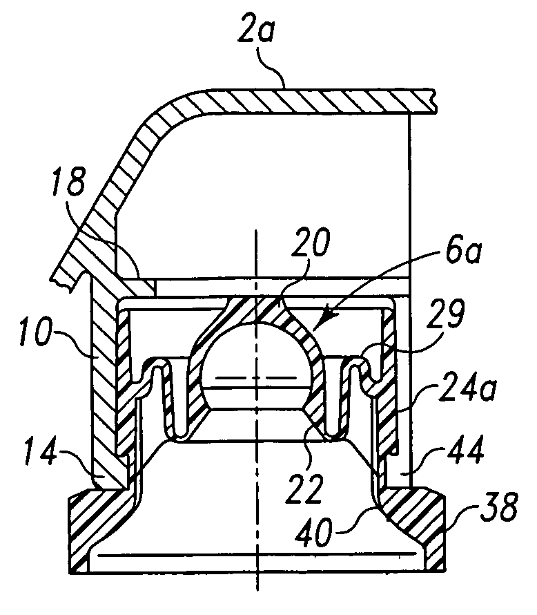
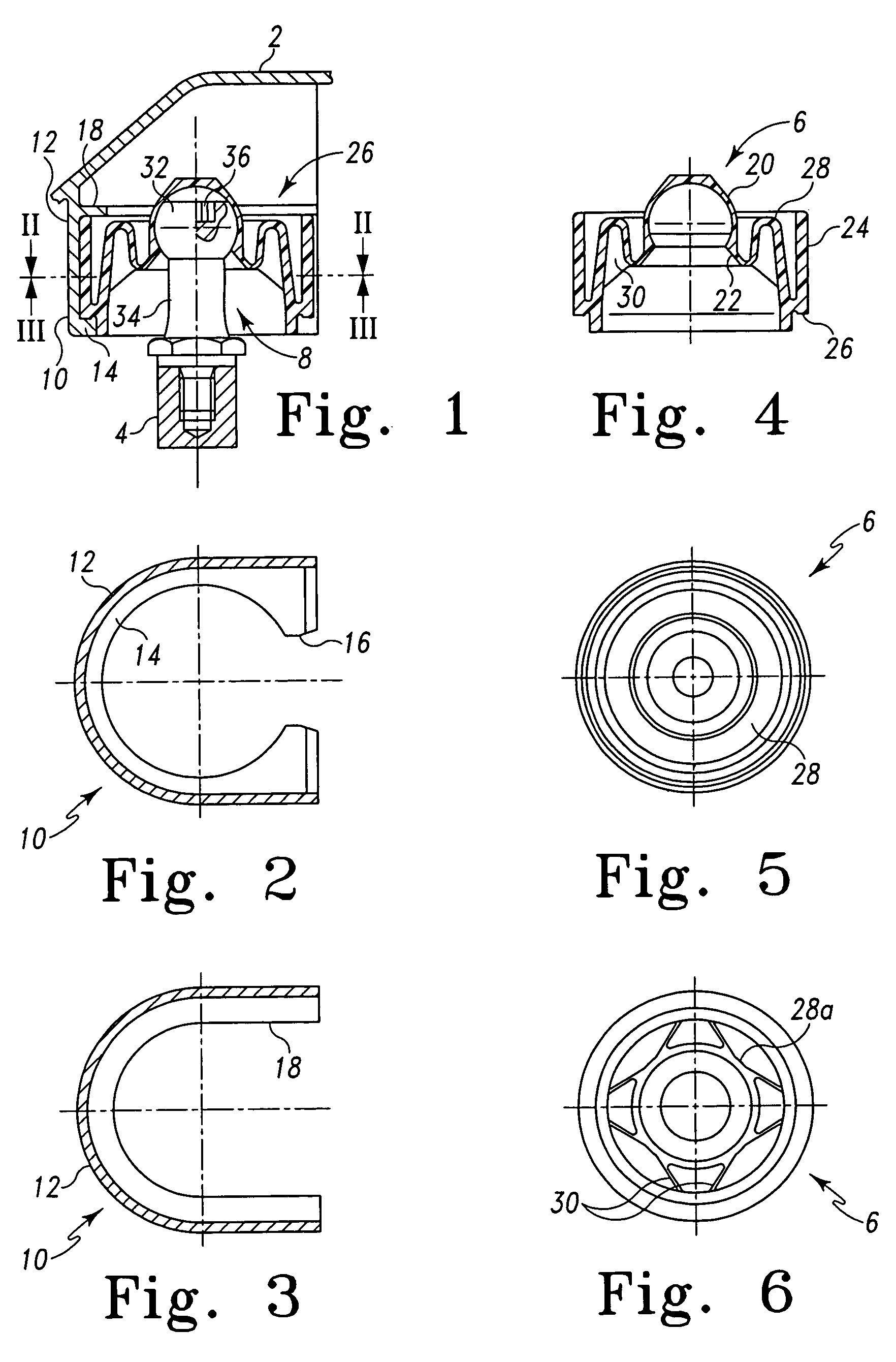
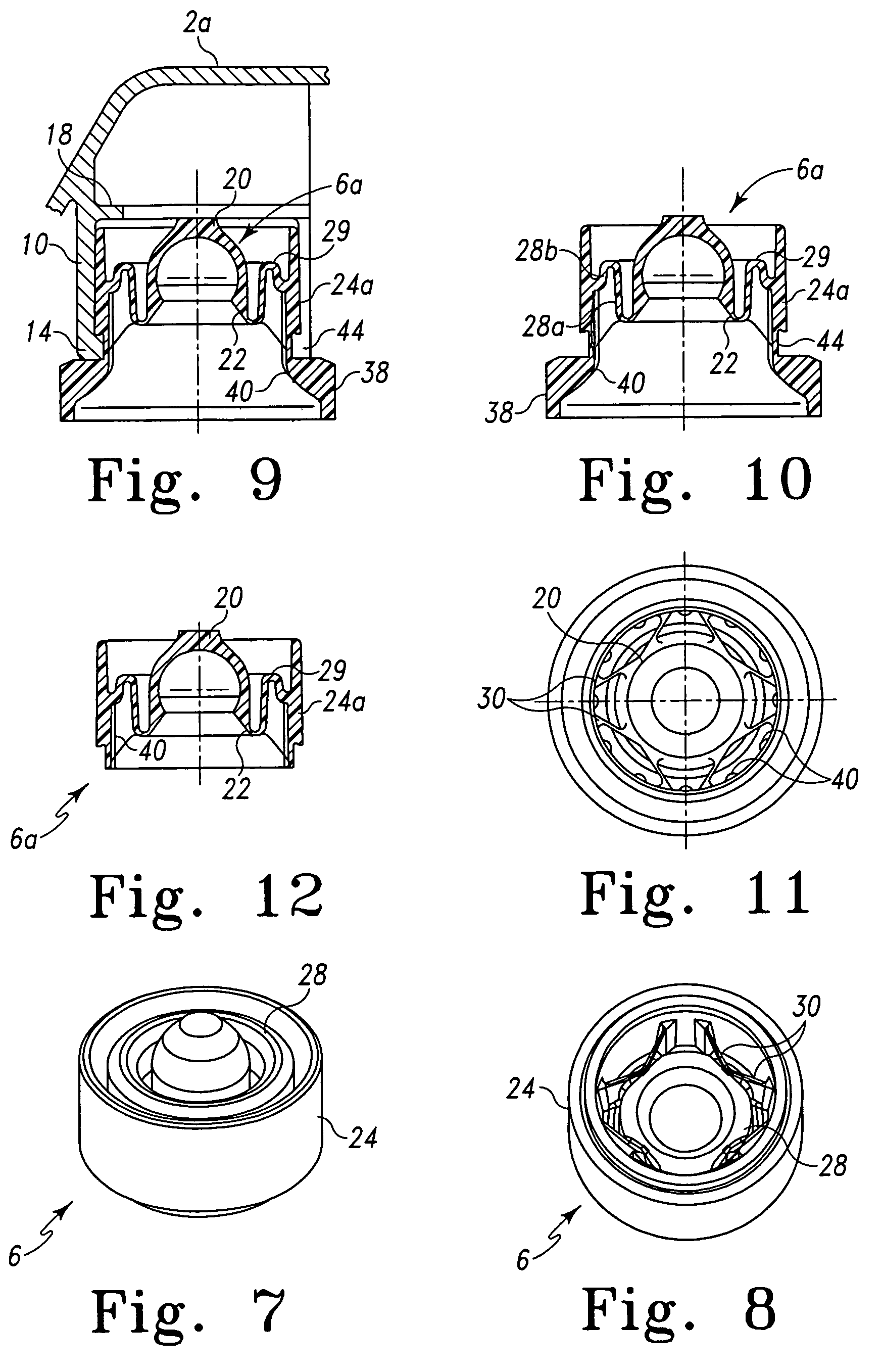
[0028]With reference to FIG. 1, the plug-in coupling shown therein is intended to removably interconnect a first structural member 2 (2a in FIG. 9) and a second structural member 4 which may be e.g. a removable cover and, respectively, a frame of an automotive vehicle (not shown). The plug-in coupling comprises a female coupling part 6 and a male coupling part 8. The female coupling part 6 is adapted to be inserted into a socket 10 of the structural member 2, and the male coupling part 8 is adapted to be secured to the structural member 4.

[0029]With further reference to FIGS. 2 and 3, the socket 10 is integral with the structural member 2 and comprises a laterally open, semi-cylindrical peripheral wall 12. At its (in FIG. 1) lower axial end the peripheral wall 12 has a radially inwards projecting integral collar 14. The collar 14 has, on one side thereof, a slot-shaped opening 16 allowing for the female coupling part 6 to be laterally inserted in the socket 10 as will be explained i...


PUM


Abstract

A plug-in coupling for removably interconnecting a first structural member and a second structural member comprises a resiliently deformable female coupling part adapted to be inserted into a socket at the first structural member such that it is retained therein. The female coupling part comprises a ball-shaped cup, an intermediate annular wall integral with said ball-shaped cup and serving as a guide portion, and a tubular external wall integral with said annular intermediate wall. The external wall surrounds at least a part of the ball-shaped cup in spaced relation thereto and engages a peripheral wall of the socket when the female coupling part is inserted into the socket. A male coupling part comprises a ball-shaped head and a fixing portion for securing the male coupling part to the second structural member. The intermediate annular wall of the female coupling part is of an undulated shape at least in a certain area thereof.

Description

BACKGROUND OF THE INVENTION[0001]The present invention relates to a plug-in coupling for removably inter- connecting a first structural member and a second structural member.[0002]Applicant's U.S. Pat. No. 6,206,604 B1 discloses a plug-in coupling comprising a resiliently deformable female coupling part and a male coupling part. The female coupling part is adapted to be inserted into a socket provided at the first structural member such that it is positively retained therein. It comprises a ball-shaped cup, a tubular external wall, and an intermediate annular wall therebetween. The tubular external wall surrounds the ball-shaped cup in spaced relationship thereto and comes into engagement with a peripheral wall of the socket when the female coupling part is inserted into the socket. The male coupling part comprises a ball-shaped head and a fixing portion adapted to be secured to the second structural member.[0003]In this plug-in coupling of the prior art, the intermediate annular wa...

Claims


Application Information

Patent Timeline
IPC IPC(8): F16C11/00F16B21/07
CPCF16B21/073Y10T403/32721Y10T403/32713Y10T403/315Y10T403/32737Y10T403/31
Inventor BERTRAM, ANDREASSUSSENBACH, RAINER
Owner BOLLHOFF GMBH
Why Eureka
Try Eureka