Battery contact mechanism including single-piece battery contact spring

a battery contact mechanism and single-piece technology, applied in the direction of connection contact member materials, cell components, coupling device connections, etc., can solve the problems of adversely affecting the operation of the device, so as to improve the ruggedness, improve the contact characteristics, and improve the effect of water resistan

Active Publication Date: 2007-01-30
GARMIN
View PDF6 Cites 13 Cited by
  • Summary
  • Abstract
  • Description
  • Claims
  • Application Information

AI Technical Summary

Benefits of technology

[0006]The present invention overcomes the problems and disadvantages in the prior art by providing a battery contact mechanism for use in a battery-power electronic device, such as, for example, a portable, hand-held global positioning system (GPS) unit or personal digital assistant (PDA). The device may include a two piece clam-shell housing providing a main compartment for housing a circuit board or other electronic componentry and a battery compartment for receiving one or more batteries for powering the electronic componentry. The mechanism advantageously provides improved contact characteristics between the battery and electronic componentry; improved ruggedness; and improved water resistance over prior art mechanisms.

Problems solved by technology

Unfortunately, the multi-piece mechanism suffers from a number of problems and disadvantages, including, for example, that the connections (i.e., solder joints) between the various pieces are weak points that can fail due to overstraining or jarring, thereby breaking the electrically-conductive pathway or connection or otherwise adversely affecting operation of the device.
Furthermore, the battery contact plate and wire are often not sufficiently secured within the device so that they loosen and move over time, thereby further adversely affecting operation.
Additionally, prior art battery contact mechanisms often do not provide a sufficient seal against moisture.
More specifically, moisture or other undesirable substances often travel on, along, or beside the wire between a battery compartment or cavity wherein the battery is located to a main compartment wherein the electronic componentry is located, thereby exposing the electronic componentry to damage.

Method used


Image

  • Battery contact mechanism including single-piece battery contact spring
  • Battery contact mechanism including single-piece battery contact spring
  • Battery contact mechanism including single-piece battery contact spring

Examples


Embodiment Construction

, below.

BRIEF DESCRIPTION OF THE DRAWINGS

[0015]Preferred embodiments of the present invention are described in detail below with reference to the attached drawing figures, wherein:

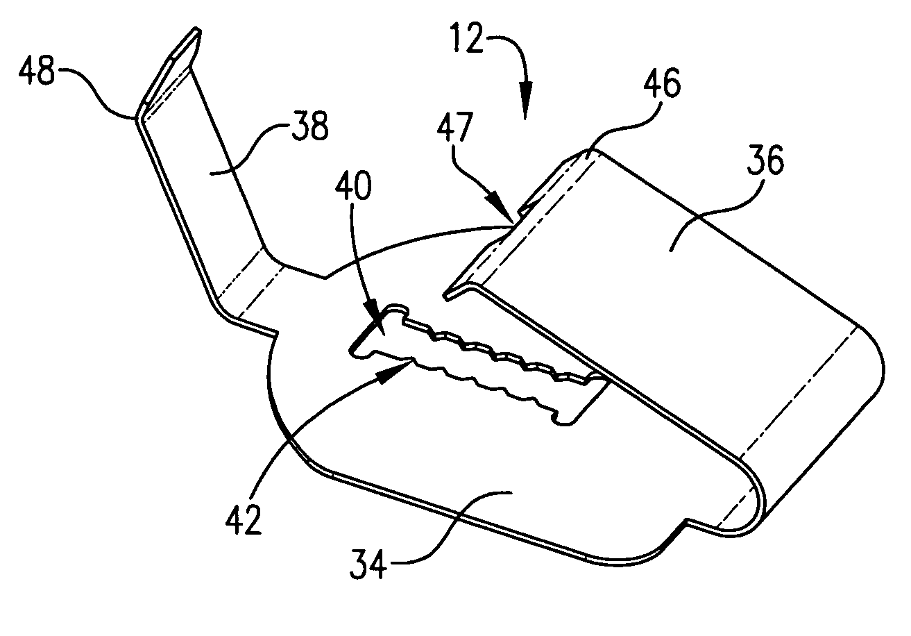
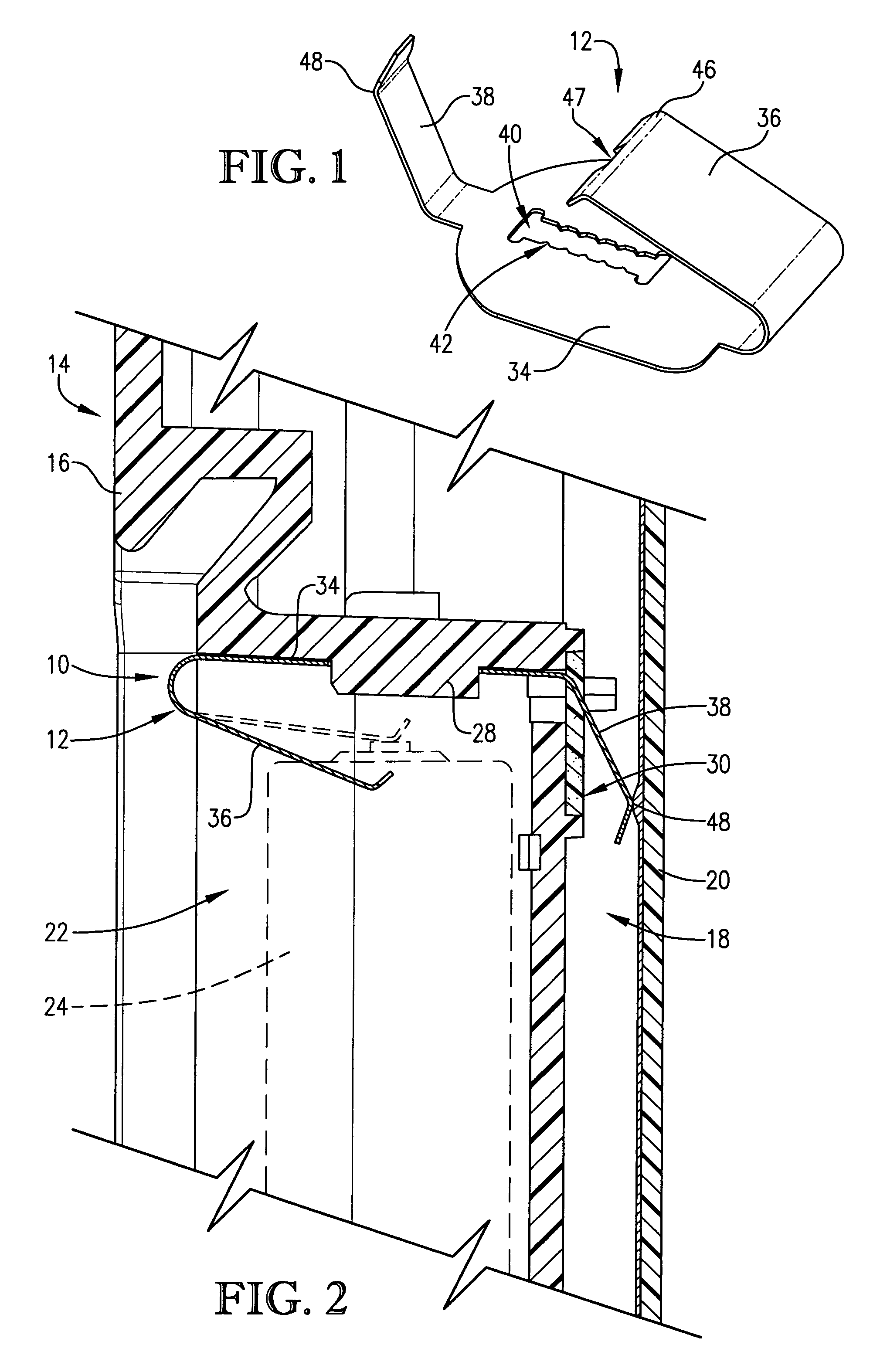
[0016]FIG. 1 is an isometric view of a battery contact spring component of a first preferred embodiment of a battery contact mechanism of the present invention;

[0017]FIG. 2 is a fragmentary sectional view of the first preferred embodiment of the battery contact mechanism installed within an electronic device, wherein a battery and a compressed position of the battery contact spring of FIG. 1 are shown in broken line;

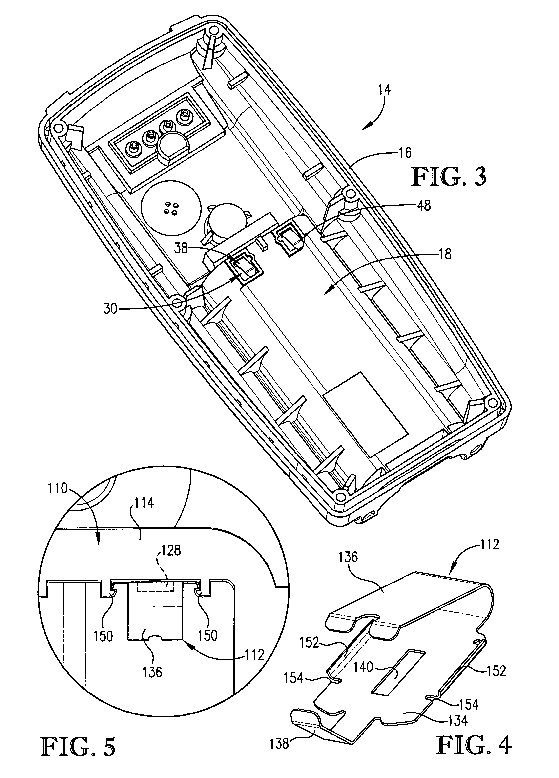
[0018]FIG. 3 is an isometric view of a bottom portion of one half of a housing of the electronic device of FIG. 2 wherein are visible a lower tang feature and sealant reservoir feature of the battery contact mechanism;

[0019]FIG. 4 is an isometric view of a battery contact spring component of a second preferred embodiment of a battery contact mechanism of the present invention; and

[0020]FIG. 5 i...


PUM


Abstract

A battery contact mechanism (10) including a battery contact spring (12) for electrically connecting a battery (24) with electronic componentry (20) within a battery-powered device (14), such as, for example, a portable, hand-held GPS unit or personal digital assistant (PDA). The battery contact mechanism (10) includes a single-piece battery contact spring (12), including a center section (34), an upper tang (36) for contacting the battery (24), and a lower tang (38) for contacting the electronic componentry (20); a post or rib projection (28) for securing the spring (12) within the device (14); and a sealant reservoir (30) for preventing leakage of moisture or other substances to the electronic componentry (20).

Description

BACKGROUND OF THE INVENTION[0001]1. Field of the Invention[0002]The present invention relates broadly to mechanisms for achieving and maintaining battery contact within a battery-powered device. More particularly, the present invention relates to a battery contact mechanism including a single-piece battery contact spring, a post projection, and a sealant reservoir for use in a battery-powered device to provide a reliable electrical connection between a battery and electronic componentry within the battery-powered device.[0003]2. Description of the Prior Art[0004]In a battery-powered device it is necessary to reliably transfer power between a battery and a circuit board or other electronic componentry. Typically, this is accomplished with a multi-piece battery contact mechanism comprising at least a contact plate for the battery, a contact pad or plate for the electronic componentry, and a wire extending between and soldered to the contact plate and pad. Unfortunately, the multi-piec...

Claims


Application Information

Patent Timeline
Patent Type & Authority Patents(United States)
IPC IPC(8): H01R4/18
CPCH01M2/1066H01R13/41H01R13/2442H04M1/0262Y02E60/10
Inventor BURRELL, JONATHAN C.WHITESIDE, JOHN B.LIN, CHI-MIN
Owner GARMIN
Why Eureka
Try Eureka