Ball and socket joint with pivoting angle sensor for detecting the relative angular position of the joint housing and the ball pivot

a technology of pivoting angle and sensor, which is applied in the direction of couplings, instruments, transportation and packaging, etc., can solve the problems of reducing the effort required for the adaptation of the angle detection system, reducing the need for maintenance, and exposing the user to extremely high mechanical loads

Inactive Publication Date: 2007-01-30
ZF FRIEDRICHSHAFEN AG
View PDF9 Cites 61 Cited by
  • Summary
  • Abstract
  • Description
  • Claims
  • Application Information

AI Technical Summary

Benefits of technology

[0010]Against this background, the object of the present invention is to provide a ball and socket joint with pivoting angle detection, in which the drawbacks are overcome, and in which especially the effort needed for the adaptation of the angle detection system can be correspondingly reduced. Shorter development times shall be achieved in this manner, and, moreover, the development, production as well as purchase and stocking costs shall be reduced.
[0013]This is extremely advantageous, because one and the same magnetic field sensor can be used essentially for a plurality of types, for example, within one series of ball and socket joint, and, moreover, the magnetic field sensor can be arranged in one and the same sensor housing as well as at one and the same location at the ball and socket joint for a plurality of types. It is readily apparent that this results in very substantial cost savings in development, stocking, production and logistics, as well as a considerable reduction of the response times to changed customer requirements.
[0016]However, a simple bar magnet, whose magnetic axis preferably coincides with the axis of the ball pivot, is preferably used as the magnet according to a preferred embodiment of the present invention. Such an embodiment is especially simple in terms of design as well as inexpensive, and leads, moreover, to a reliable angle detection, which remains unaffected by a possibly occurring rotation of the ball pivot about its own axis during the operation of the ball and socket joint. The magnet is arranged especially preferably in the pole area of the joint ball that is located opposite the ball pivot.
[0018]This is advantageous, just as the above-described arrangement of the magnet, in terms of a simple design of the ball and socket joint, as well as for the reliable detection of the pivoting angle, independently from a possible rotation of the ball pivot in the joint housing. The magnetic field sensor is preferably arranged in a plastic element or is embedded in a plastic element. The plastic element can especially assume at the same time the function of the closing cover for the joint housing on the side of the joint housing located opposite the ball pivot, which in turn serves the purpose of simplifying the design and of correspondingly saving costs and of increasing the reliability of the ball and socket joint.
[0022]According to another embodiment of the present invention, the elastic auxiliary body may, furthermore, also be designed as an essentially annular spring, consisting of a preferably non-ferromagnetic material, and, according to another embodiment, the annular spring may, moreover, be extrusion-coated with a plastic material at least in some areas for receiving the magnet. On the one hand, the magnet can thus be mounted in an especially simple manner, and, on the other hand, an especially vibration-resistant anchoring of the magnet in the joint ball is achieved with an annular spring, especially with an extrusion-coated spring.
[0023]The embedding of the magnet in the joint ball by means of an essentially cylindrical ring-shaped or annular auxiliary body or with an essentially annular spring is especially advantageous in that the position and the size of the magnet as well as the position and the size of the recess in the joint ball, on which the shape, the strength and the extension of the magnetic field depend considerably, can thus be optimized in an especially simple manner and, moreover, independently from one another, so that precisely the characteristic magnetic field necessary for the maximum resolution of the pivoting angle sensor will develop.

Problems solved by technology

Moreover, due to their arrangement in the area of the chassis, ball and socket joints of this class are, however, also exposed to extremely high mechanical loads, for example, due to vibrations, as well as to strong effects of environmental media, such as moisture, sand or de-icing salt.
Nevertheless, users require long service life, fail-safe operation and elimination of the need for maintenance along with low costs.
However, such an application-specific design of all the components of such a ball and socket joint, which determine the angle detection, is complicated and expensive.

Method used


Image

  • Ball and socket joint with pivoting angle sensor for detecting the relative angular position of the joint housing and the ball pivot
  • Ball and socket joint with pivoting angle sensor for detecting the relative angular position of the joint housing and the ball pivot
  • Ball and socket joint with pivoting angle sensor for detecting the relative angular position of the joint housing and the ball pivot

Examples


Embodiment Construction

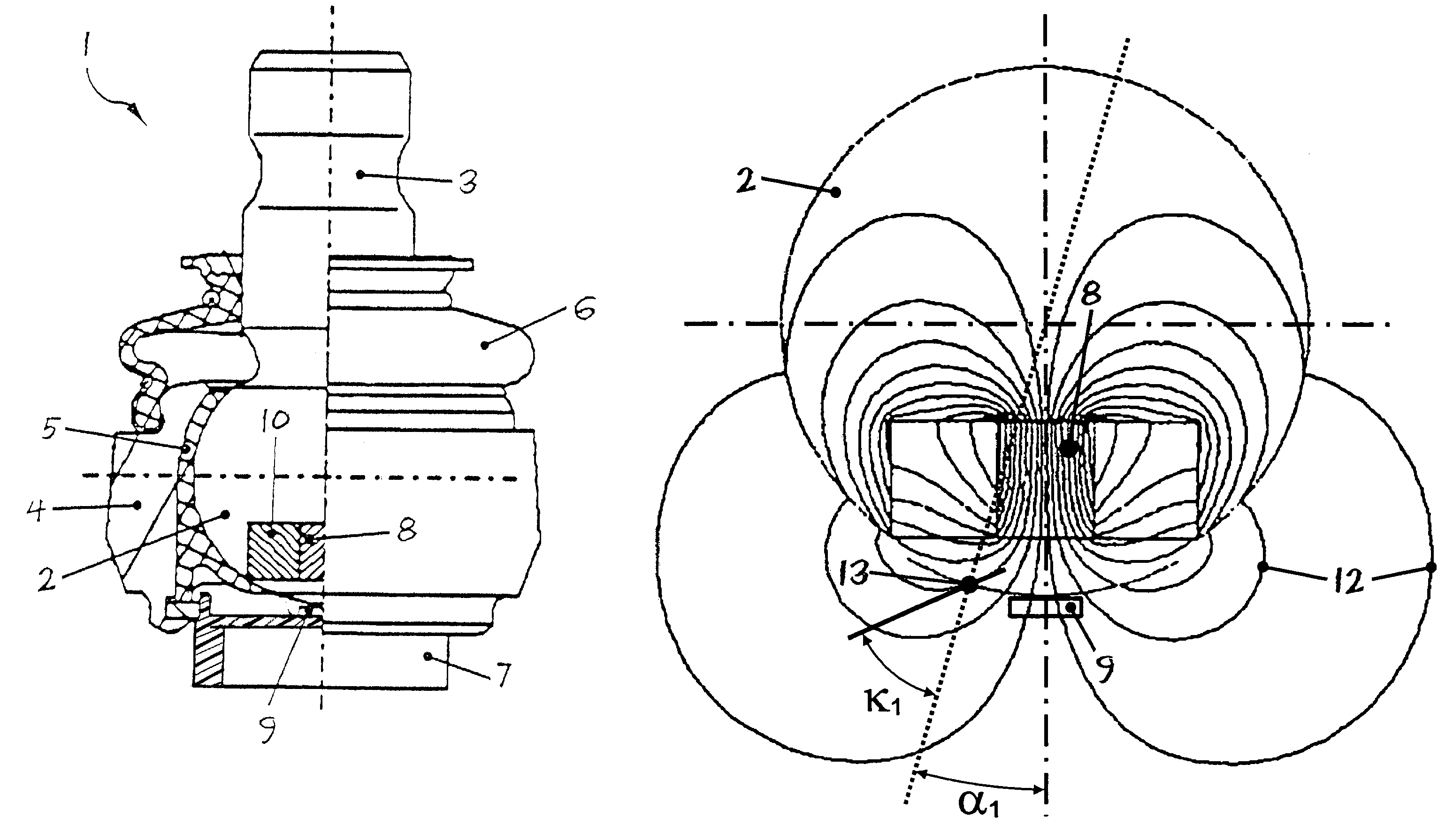
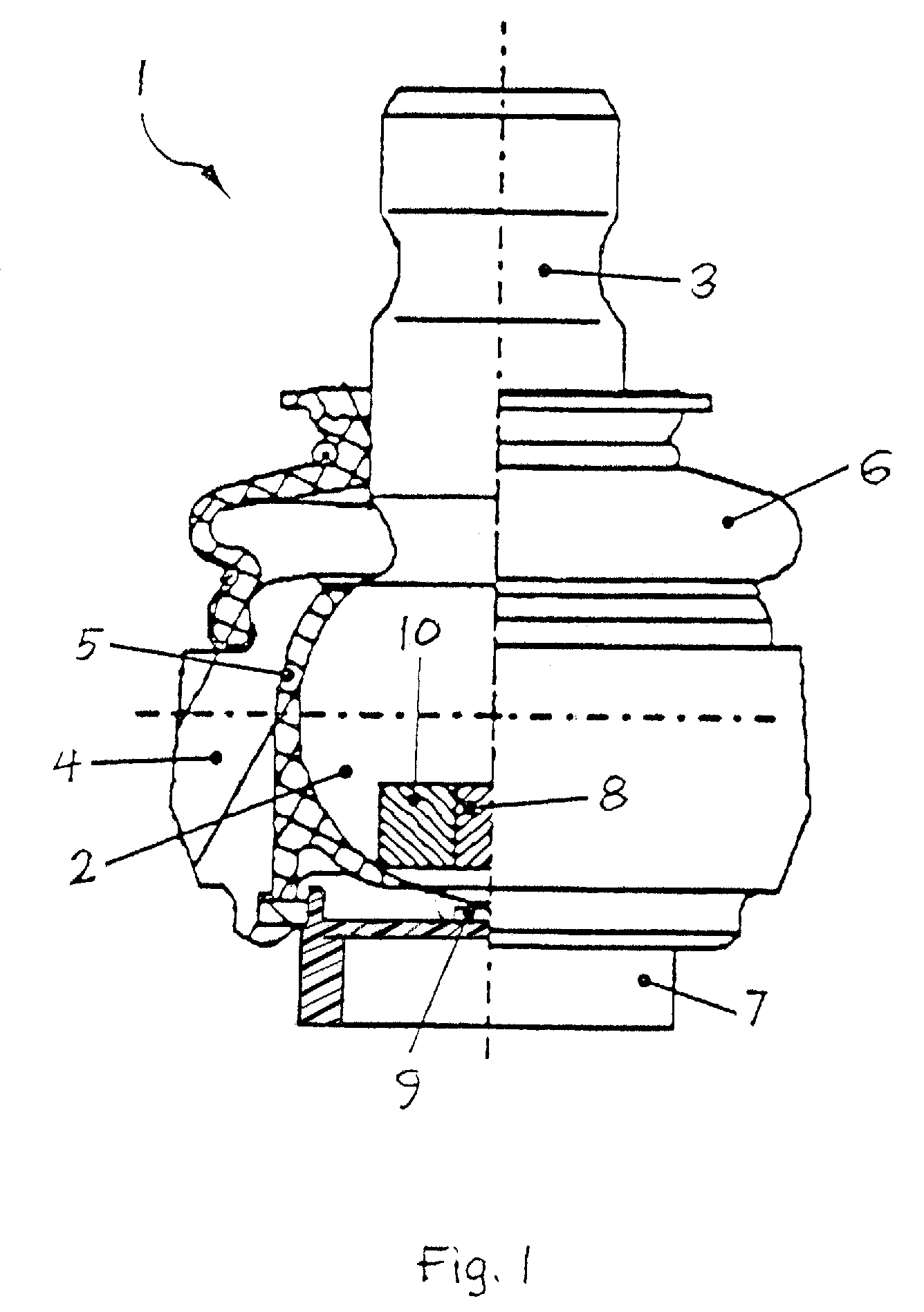
[0037]Referring to the drawings in particular, FIG. 1 shows a partially longitudinally cut-away view of a ball and socket joint 1. The ball and socket joint 1 is composed essentially of the ball pivot 3 comprising the joint ball 2 and the joint housing 4 with the bearing shell 5 inserted therein. Furthermore, the ball and socket joint 1 also comprises an elastomer bellows 6 and a housing cover 7, which are used to protect the joint ball 2 and the bearing shell 5 against the penetration of dirt and moisture.

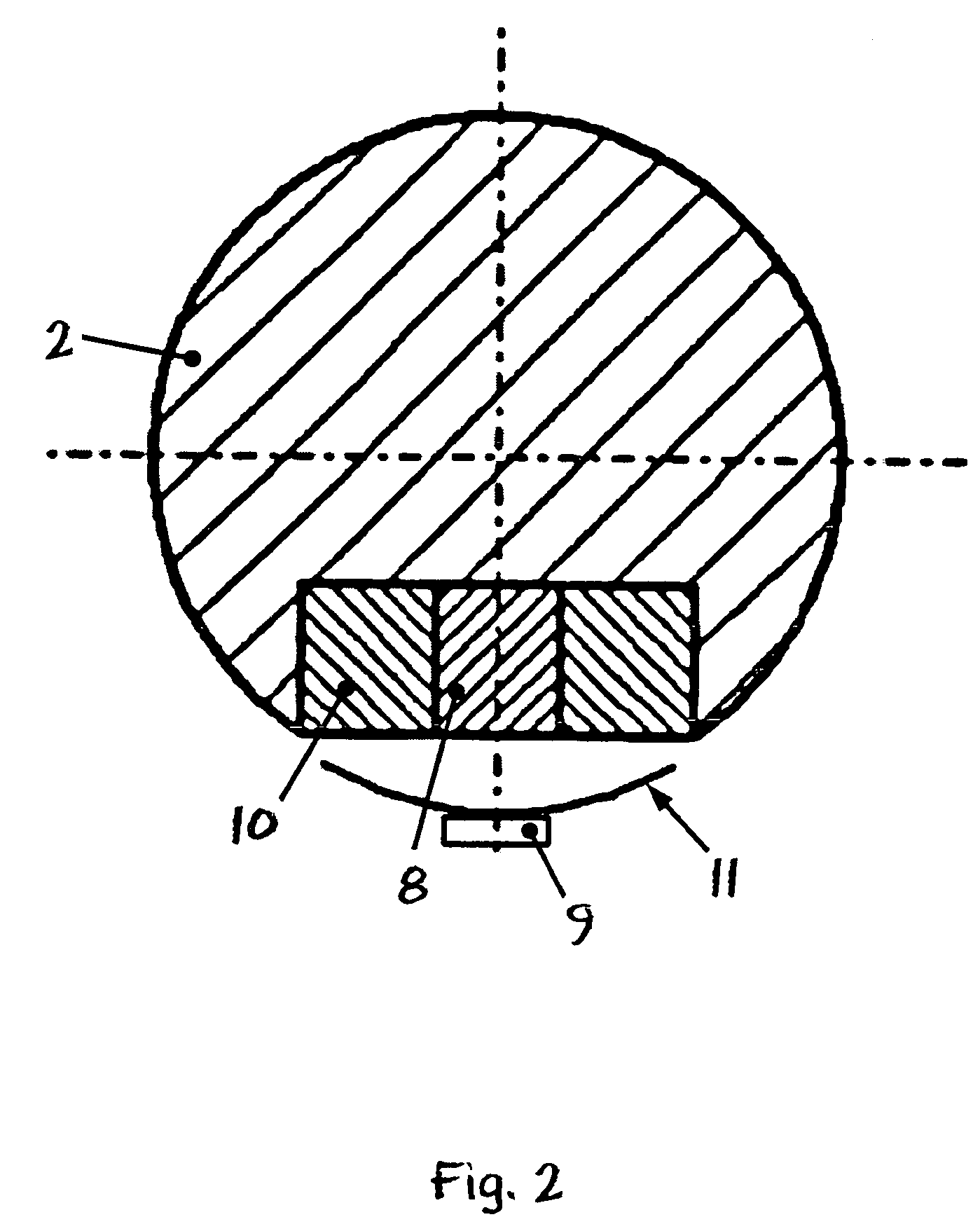
[0038]Moreover, the ball and socket joint 1 is also provided, however, with a means for detecting the pivoting angle position of the ball pivot 3 in relation to the joint housing 4. This angle measuring means comprises, on the one hand, a permanent magnet 8, which is arranged in the pole area of the joint ball 2, which said pole area faces away from the pivot, in a recess of the joint ball 2 which is present there. On the other hand, the angle measuring means comprises a magnetic ...


PUM


Abstract

A ball and socket joint (1) is provided with a pivoting angle sensor (9) for detecting the relative angular position of the joint housing (4) and the ball pivot (3). The pivoting angle α of the joint ball (2) is detected by a measuring means comprising a magnet (8) and a magnetic field sensor (9). The position and the size of the magnet (8) as well as the position and the size of the recess of the joint ball (2) are selected for each type of ball and socket joint from one series such that when the particular nominal pivoting angle αm of the ball and socket joint (1) is reached, the angle κ of the magnetic field lines (12) passing through the magnetic field sensor (9) approximately equals a constant κm, which applies to the entire series. As a result, one and the same magnetic field sensor (9) can be used within the entire series of ball and socket joints for a plurality of types and it can be arranged in one and the same sensor housing (7) as well as at one and the same location at the ball and socket joint (1) for a plurality of types. Among other things, considerable cost savings are achieved because of the resulting reduction in the number of parts and the simplification of the design of the series of ball and socket joints.

Description

CROSS REFERENCE TO RELATED APPLICATION[0001]This is a continuation of and claims the benefit (35 U.S.C. §120 and 365(c)) of copending International Application PCT / DE 2004 / 001800 of Aug. 11, 2004, which designated inter alia the United States and which claims the priority of German Application DE 103 38 833.8 of Aug. 21, 2003. The entire contents of each application is hereby incorporated by reference in its entirety.FIELD OF THE INVENTION[0002]The present invention pertains to a ball and socket joint with a pivoting angle sensor for detecting the relative angular position of the joint housing and the ball pivot.BACKGROUND OF THE INVENTION[0003]Ball and socket joints of the type mentioned in the introduction are used, for example, but by no means exclusively, on the chassis of motor vehicles. Such ball and socket joints with pivoting angle sensor are used, for example, to detect the relative positions of different chassis parts in relation to one another or the relative position of,...

Claims


Application Information

Patent Timeline
Patent Type & Authority Patents(United States)
IPC IPC(8): G01B7/30B60G7/00B60G17/019F16C11/06G01D5/14G01D5/16
CPCB60G7/005B60G17/019F16C11/0619G01D5/145B60G2204/11Y10T403/32631B60G2401/172B60G2204/416F16C41/007F16C11/0633F16C2326/05F16C11/0609F16C11/06G01D5/12
Inventor SPRATTE, JOACHIM
Owner ZF FRIEDRICHSHAFEN AG
Why Eureka
Try Eureka