Electronic fuse blow mimic and methods for adjusting electronic fuse blow

a technology of electronic fuse blow and imitation, which is applied in the direction of fuses testing, emergency protective devices, instruments, etc., can solve the problems of two undesirables and the current state of art technology providing no satisfactory solution to determin

Inactive Publication Date: 2007-01-30
IBM CORP
View PDF6 Cites 28 Cited by
  • Summary
  • Abstract
  • Description
  • Claims
  • Application Information

AI Technical Summary

Problems solved by technology

Using a “one size fits all” approach to a fuse blow will probably result in two undesirable results, i.e., ruptured fuse or weak fuse blow.
However, the current state of art technology provides no satisfactory solution to determine whether and how an environmental variable needs to be varied.

Method used


Image

  • Electronic fuse blow mimic and methods for adjusting electronic fuse blow
  • Electronic fuse blow mimic and methods for adjusting electronic fuse blow
  • Electronic fuse blow mimic and methods for adjusting electronic fuse blow

Examples


Embodiment Construction

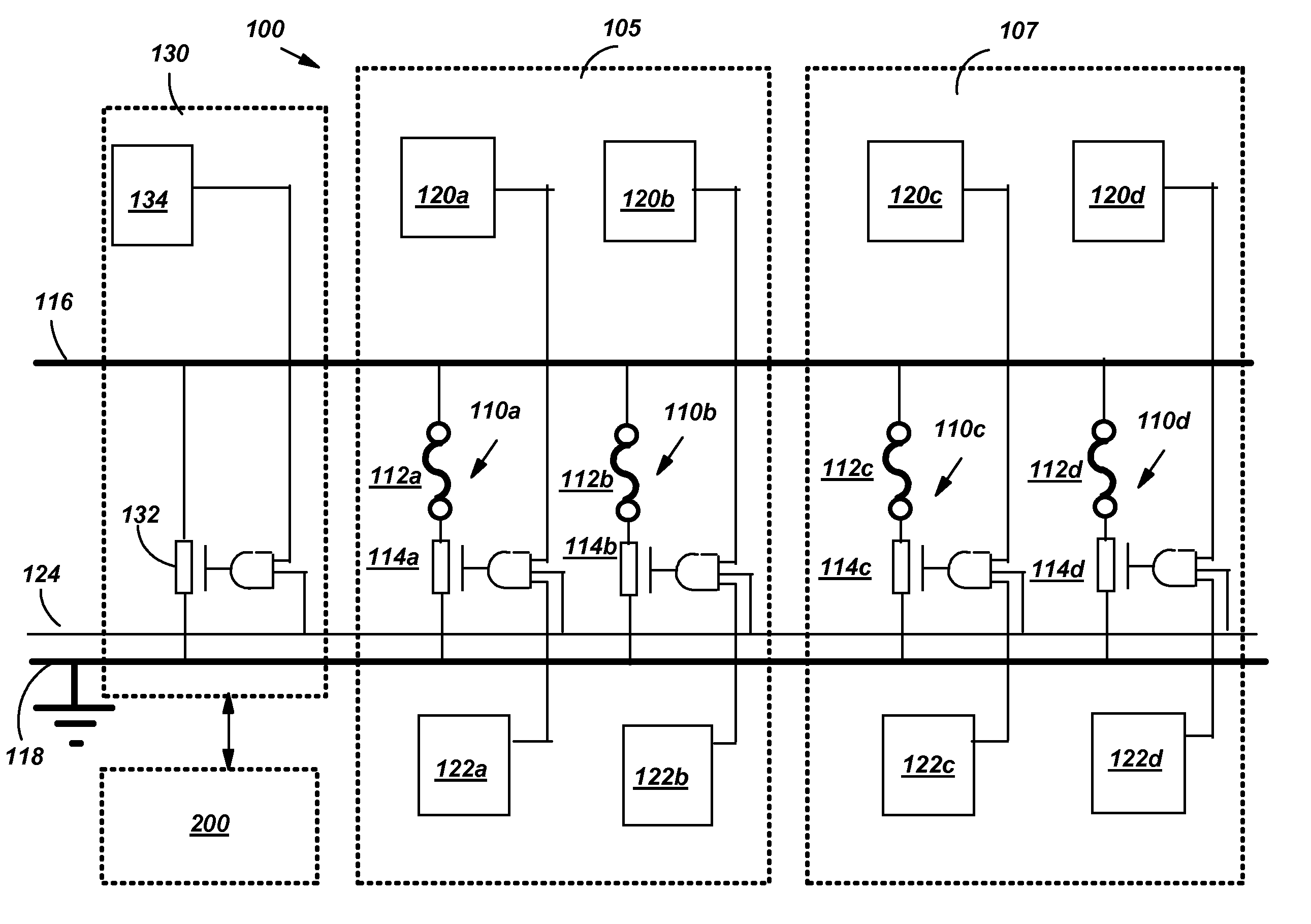
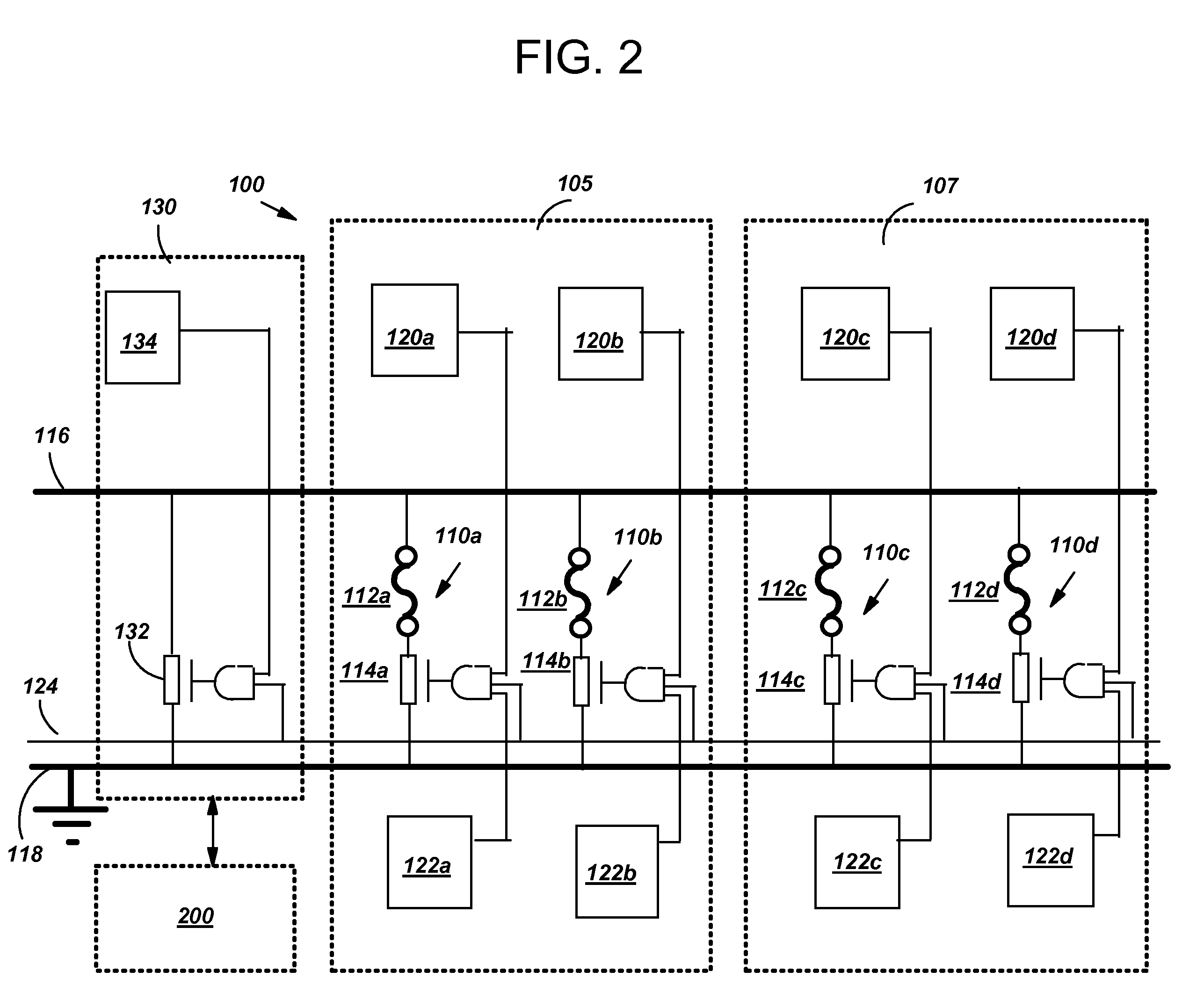
[0018]Turning to the drawings, FIG. 2 shows an illustrative embodiment of a hardware implementation system 100 for mimicking an electronic fuse blow. As is known in the art, an application specific integrated circuit (ASIC) may include, among other components, an electronic chip identification (ECID) macro which contains electronic fuses. The ASIC may also include electronic fuses present for the purpose of implementing certain redundancy structures, such as structures commonly found in memory arrays (i.e. redundant wordlines or redundant columns). The fuses may be blown to disconnect a normal wordline and replace it with a redundant wordline if, for example, the normal wordline is detected as defective. In FIG. 2, implementation system 100 includes electronic fuses (110a and 110b) within an ECID macro 105, and electronic fuses (110c and 110d) within a redundancy fuse bay 107 of an integrated circuit chip (not shown), for illustrative purpose only. Each fuse (110a–110d) includes a p...


PUM


Abstract

A system, method and program product for adjusting an environmental variable of a fuse blow of an electronic fuse are disclosed. A mimic NFET is coupled to a fuse blow source voltage line, a fuse blow gate voltage line, and a chip ground in the same manner as the electronic fuse, except that the mimic NFET is not attached to a poly fuse link. The on current (ion) and off current (ioff) of the mimic NFET are measured to determine a blow current of the electronic fuse. The environmental variable is adjusted based on the determined blow current.

Description

BACKGROUND OF THE INVENTION[0001]1. Technical Field[0002]The invention relates generally to electronic fuse blow, and more particularly, to a method and system for mimicking an electronic fuse blow and adjusting the same.[0003]2. Background Art[0004]An electronic fuse is basically a poly silicon fuse link which is coupled to a voltage line (usually referred to as a FSource) on one end, and to the top of an n-channel field-effect transistor (NFET) on the other end. FIG. 1 shows a configuration of an electronic fuse 10 including a poly silicon fuse link 12 and an NFET 14. NFET 14 of fuse 10 is usually referred to as a blowFET 14. The gate of blowFET 14 is coupled to a gate voltage 24. During a fuse blow, a voltage is supplied by the FSource and NFET 14 is turned on by, inter alia, a gate voltage (Vdd or blow Vdd) 24, for a particular amount of time, which allows controlled electromigration to occur, which causes a salicide / boron pile-up on an anode side (not shown) of poly fuse link 1...

Claims


Application Information

Patent Timeline
Patent Type & Authority Patents(United States)
IPC IPC(8): H01H85/30G01R31/00H01H85/00
CPCG11C17/16G11C17/165G11C29/02G11C29/027G11C29/028G11C17/18G01R31/07H01L23/5256H01L2924/0002G01R31/74H01L2924/00
Inventor ANAND, DARREN L.OUELLETTE, MICHAEL R.PERRY, TROY J.
Owner IBM CORP
Why Eureka
Try Eureka