Multi-way LED-based surface reflectance sensor and spectrophotometer

a surface reflectance sensor and led-based technology, applied in the field of surface reflectance sensors, can solve the problems of increasing the cost, size and power requirements of the system, and the most expensive component of the system, and achieve the effect of less photocurren

Inactive Publication Date: 2007-01-30
MITSUBISHI ELECTRIC RES LAB INC
View PDF11 Cites 25 Cited by
  • Summary
  • Abstract
  • Description
  • Claims
  • Application Information

AI Technical Summary

Benefits of technology

[0010]The present invention provides an inexpensive surface reflectance sensing system with a high dynamic range, and a low power requirement. The system is particularly suited for applications where there is a minimal amount of light.
[0017]As an advantage, an LED is generally equally sensitive to all wavelengths equal or shorter than an emission wavelength of the LED. Light at longer wavelengths generates significantly less photocurrent. For example, a yellow LED responds almost equally well to yellow, green, blue light, and ultraviolet light, but does not respond to orange, red, or infrared light. Therefore, a very inexpensive coarse-resolution spectrograph can be constructed by using concurrently several LEDs tuned to different colors.
[0018]In this embodiment, each LED sensor responds only to wavelengths equal to or shorter than the emission wavelength of the sensor. Thus, it is possible to reconstruct the per-band light intensities, or spectra, of the incident light.
[0019]As an additional advantage, the LEDs can be switched rapidly between emitting and sensing modes. In this way, longer-wavelength LEDs can be used both as sensors for shorter wavelength LEDs, as well as emitters for yet longer wavelength LEDs. In this configuration, material to be tested reflects emitted light to one or more sensor LEDs. Thus, the LEDs can operate as narrow-band emitters and as a high-pass sensor using the same circuit.
[0020]As another advantage, a filtering element, such as a UV-blocking filter, can be added so that the system operates as a fluorescence sensor. In this embodiment, a widest-band-sensitivity LED is used, e.g., a red or infrared LED, which can sense respectively all visible light, or all visible and near infrared wavelengths. More than one LED can be used with the UV-blocking filter to provide a coarse resolution fluorescence spectrograph.
[0022]As another advantage, the LEDs can be switched rapidly between emitting and sensing modes, e.g., less than a microsecond. In this way, differential measurements can be acquired, where the sensor measures transmitted or reflected light in both the presence and absence of an excitation source, and the actual useful signal is a difference function of the two signals.

Problems solved by technology

There, the A / D converter is the most expensive component of the system.
Although, that type of system is less expensive, the small number of available colors available, e.g., five, makes it less suitable for analytical work.
That substantially increases the expense, size and power requirements of the system.
Therefore, a proportional filter is used to ‘flatten’ the response to match that of the human eye, which decreases the sensitivity of the system.
Furthermore, the dynamic range of a conventional 16-bit converter is roughly 64,000:1, with a considerable power consumption.

Method used


Image

  • Multi-way LED-based surface reflectance sensor and spectrophotometer
  • Multi-way LED-based surface reflectance sensor and spectrophotometer
  • Multi-way LED-based surface reflectance sensor and spectrophotometer

Examples


Embodiment Construction

[0032]Basic Bi-Directional LED Sensor Circuit

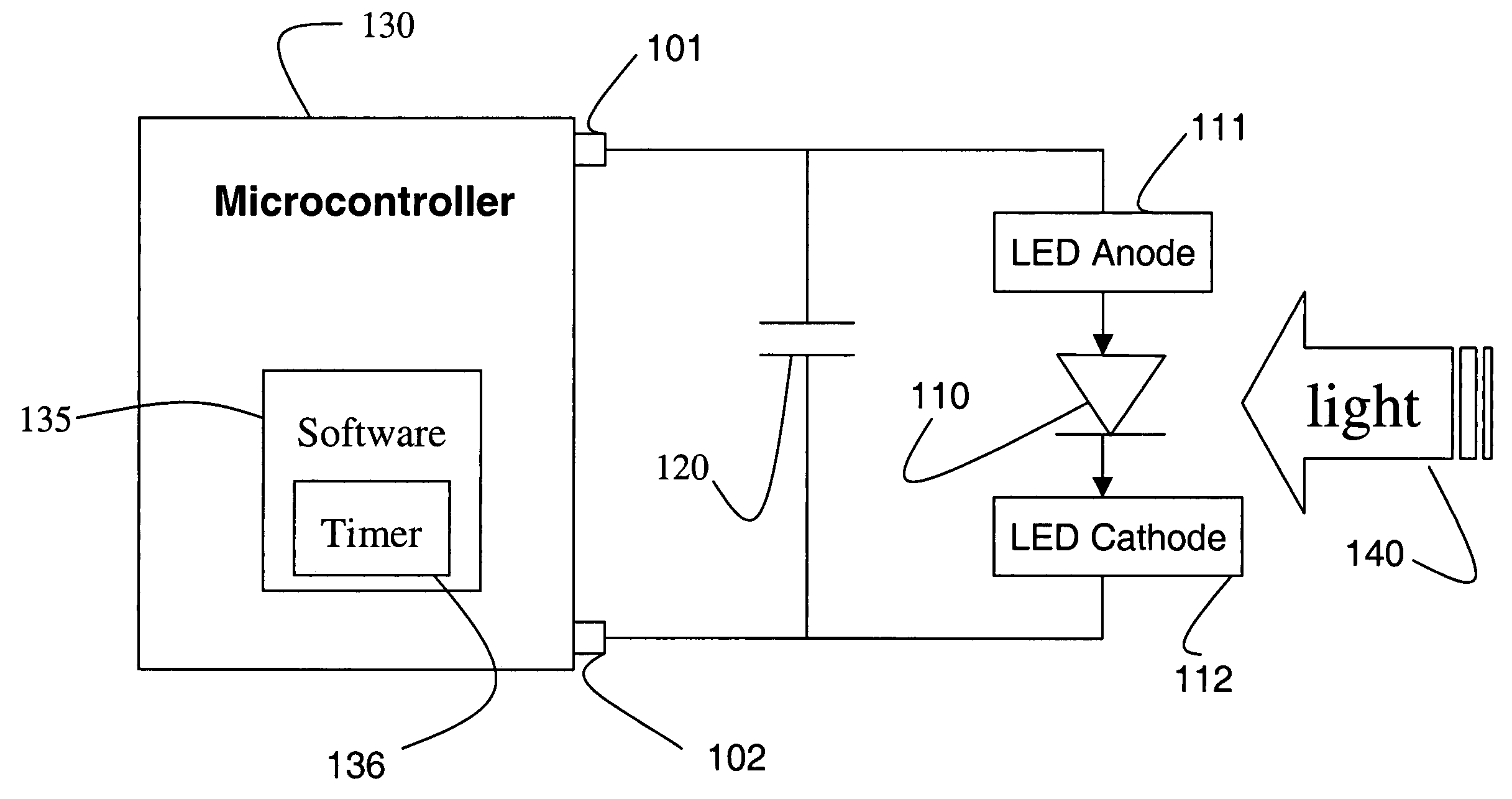
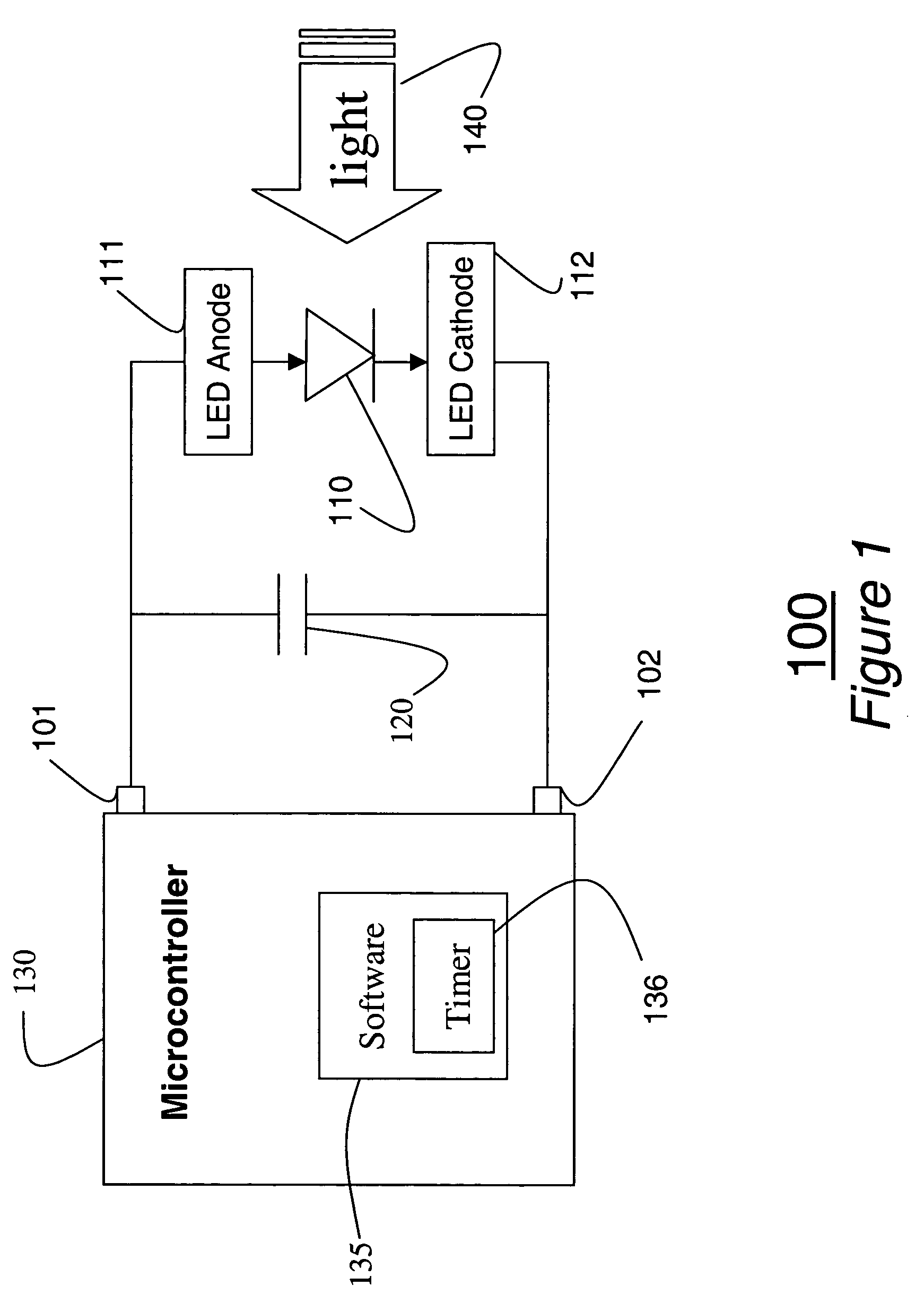
[0033]FIG. 1 shows an LED-based light sensor 100 according to the invention. The sensor includes an LED 110, a capacitor 120, and a microcontroller 130. An anode 111 of the LED 110 is connected to a bi-directional digital I / O pin 101 of the microcontroller. A cathode 112 is connected to another pin 102. The state of current on the I / O pins 101–102 determines whether the LED 110 emits or senses light. For a detailed description of light emitting diodes operating as both an emitter and a sensor see U.S. patent application Ser. No. 10 / 126,761 “Communication Using Bi-Directional LEDs,” filed by Dietz et al. on Apr. 19, 2002, incorporated herein by reference in its entirety.

[0034]The microcontroller 130 can be a MicroCircuits Inc. PIC 16F876 processor, which as multiple data pins. The microcontroller 100 also has conventional power and communication connections. These connections are not shown for clarity. The microcontroller can execute softw...


PUM

PropertyMeasurementUnit
parasitic capacitanceaaaaaaaaaa
impedanceaaaaaaaaaa
widthaaaaaaaaaa

Abstract

A light sensor circuit based on direct connection of LEDs to I / O pins of a microcontroller. The LEDs are reverse biased and the parasitic junction capacitance is charged in an output mode. Then, the I / O pins placed into an high-impedance input mode. The time for the capacitance to be discharged by photoconduction caused by light incident on the LEDs is inversely proportional to an intensity of the incident light, and can be directly measured as the time required for the I / O pin to transition from fully-charged (5 volts) to a logic threshold level (1.7 volts). By using multiple LEDs, multiplexed between emissive and sensing modes, a wide variety of sensors can be constructed, particularly, when the LEDs emit light at different wavelength.

Description

RELATED APPLICATION[0001]This application is a Continuation-in-Part Application of U.S. patent application Ser. No. 10 / 251,251, titled “Multi-Way LED-Based Chemochromic Sensor,” filed by Yerazunis et al. on Sep. 20, 2002 now U.S. Pat. No. 7,008,795.FIELD OF THE INVENTION[0002]This invention relates generally to surface reflectance sensors and more particularly to LED-based surface reflectance sensors and spectrophotometersBACKGROUND OF THE INVENTION[0003]With a surface reflectance sensing system, a material to be tested is illuminated by a light source, and reflected light is measured with a light sensor. The light can be monochromatic, a range of wavelengths, or a mixture of wavelengths, such as ‘white’ light. This can be accomplished either by filtering the emitted light or the sensed light.[0004]For example, the light source can be a wide-band tungsten-halogen or a tungsten-deuterium light that is filtered. The filtered light is transmitted to the surface, and then reflected and ...

Claims


Application Information

Patent Timeline
Patent Type & Authority Patents(United States)
IPC IPC(8): G01N21/00C12Q1/68G01J1/00H01J43/00G01B11/24G01J1/44G01N21/78
CPCG01N21/78
Inventor YERAZUNIS, WILLIAM S.
Owner MITSUBISHI ELECTRIC RES LAB INC
Why Eureka
Try Eureka