Scanning ultrasound detection device using two-wave mixing in photorefractive crystal interferometry

a detection device and photorefractive crystal technology, applied in ultrasonic/sonic/infrasonic diagnostics, instruments, applications, etc., can solve problems such as complex inspection process, damage to the whole package of a tested sample (e.g. an ic for inspection), and reduce the cost of volume production, increase system reliability, and compact structur

Inactive Publication Date: 2007-01-30
IND TECH RES INST
View PDF4 Cites 2 Cited by
  • Summary
  • Abstract
  • Description
  • Claims
  • Application Information

AI Technical Summary

Benefits of technology

[0009]It is another object of the present invention to provide a scanning ultrasound device using TWM i

Problems solved by technology

The inspection for defects in material structures is always a critical issue for monitoring and controlling quality in the manufacturing industry.
In the conventional destructive inspection for defects, the whole package of a tested sample (e.g. an IC for inspection) is destructively ta

Method used


Image

  • Scanning ultrasound detection device using two-wave mixing in photorefractive crystal interferometry
  • Scanning ultrasound detection device using two-wave mixing in photorefractive crystal interferometry
  • Scanning ultrasound detection device using two-wave mixing in photorefractive crystal interferometry

Examples


Embodiment Construction

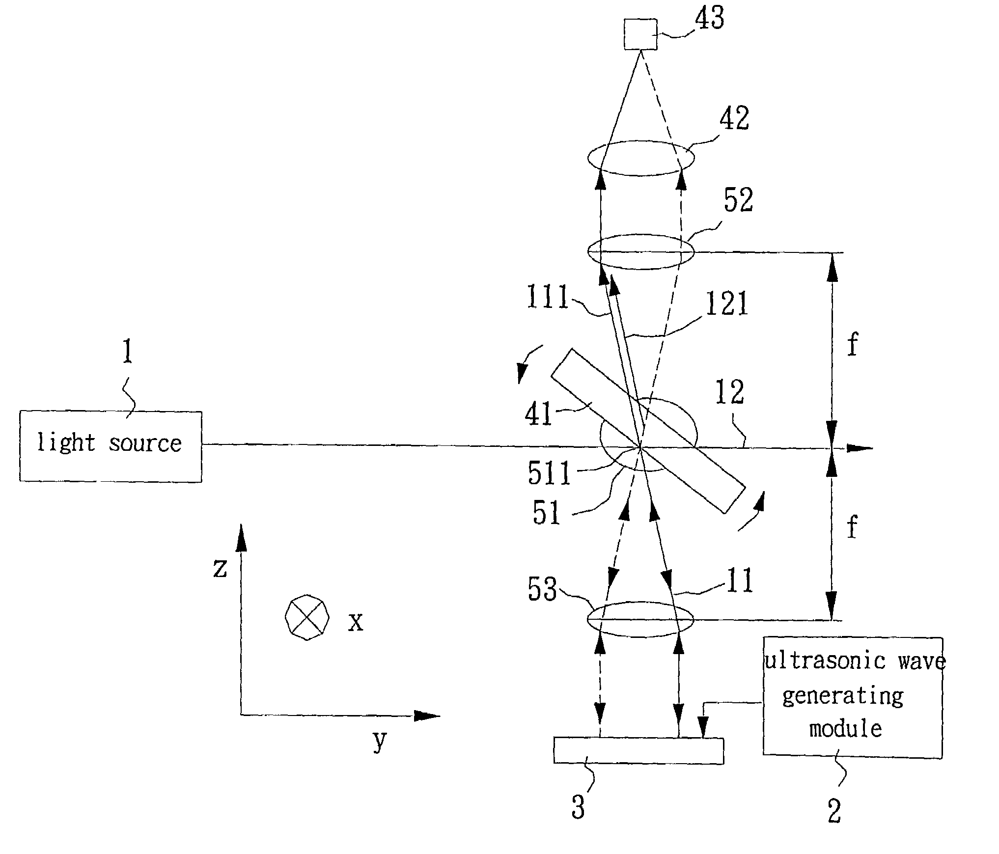
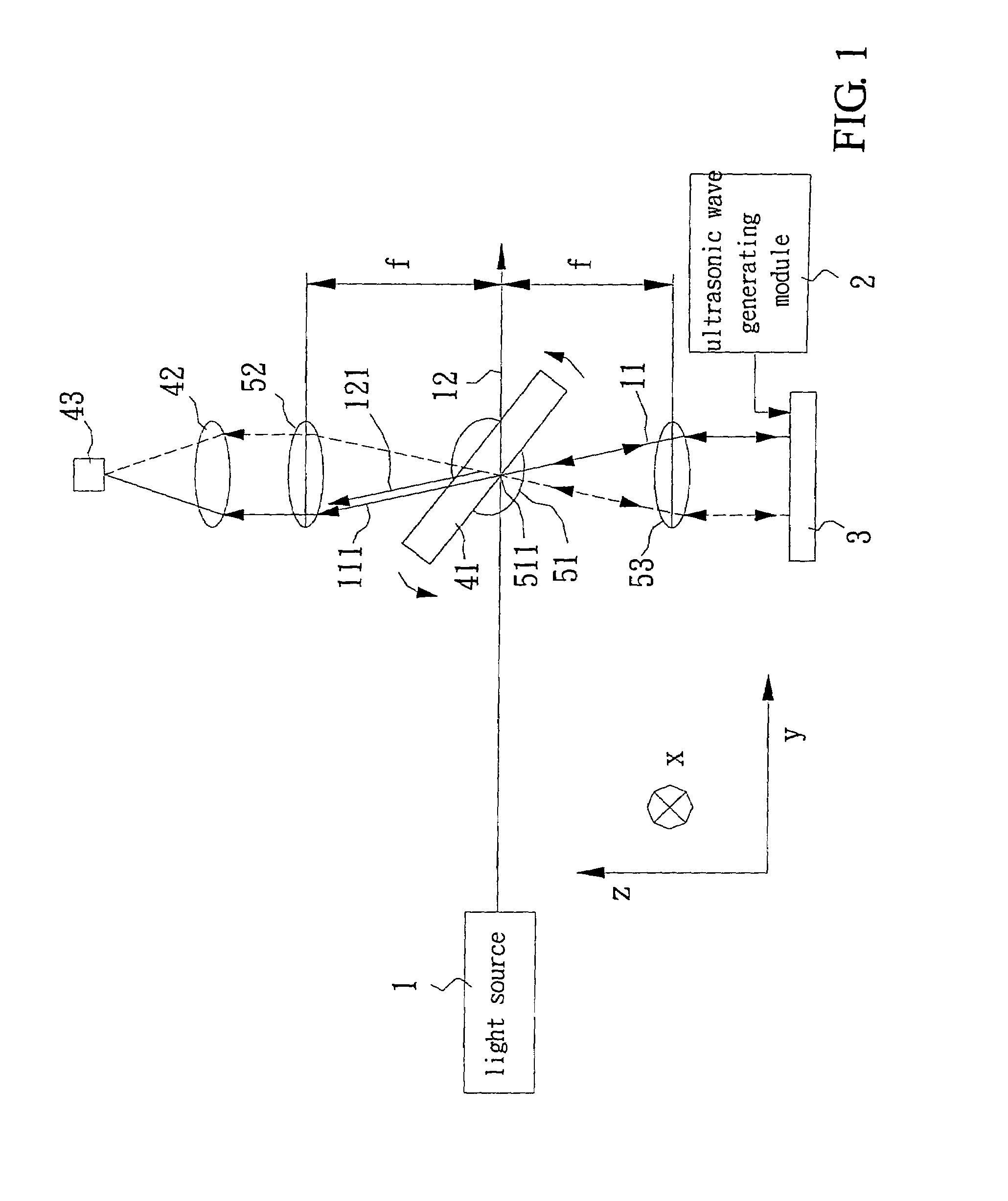
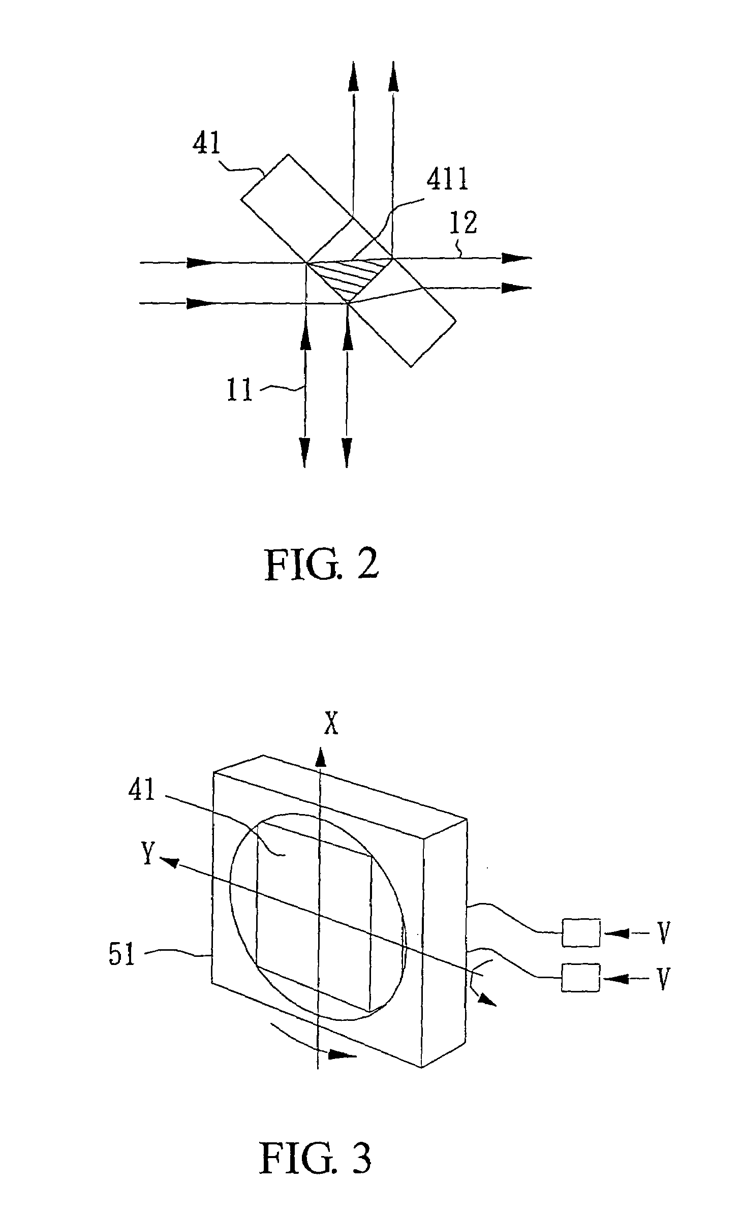
[0015]FIG. 1 shows the structure of a preferred embodiment according to the present invention, and provides a schematic view of the structure. The scanning ultrasound device comprises a light source 1, an ultrasound-wave-generating-module 2, a photorefractive crystal 41, a first convex lens 42, a second convex lens 52, a third convex lens 53, a rotating mechanism 51 and a photo detector 43. The photorefractive crystal 41 is supported in the rotating mechanism 51, having a rotation axis 511 where the focal point of the second convex lens 52 and the focal point of the third convex lens 53 are located. The photo detector 43 is mounted at the focal point of the first convex lens 42. As shown in FIG. 1, the first convex lens 42 locates on a position opposed to the focal point of the second convex lens 52 and the focal point of the third convex lens 53. In this embodiment, the light source 1 preferably is a continue wave (CW) laser. When the light source 1 strikes on the photorefractive c...


PUM


Abstract

This invention relates to a scanning ultrasound detection device using two-wave mixing in photorefractive crystal interferometry. An interferometer with two-wave mixing in photorefractive crystal, and cooperates with a confocal lenses module to perform a scan and inspection of the surface of a target. A rotating unit is used for directing a signal beam for detection to be incident upon different locations of the target. The confocal lens module is used to compensate any changes of reflection path caused by the signal beam having different incident angles. Hence, a reflected signal beam and a reference beam can strike on a photo detector.

Description

BACKGROUND OF THE INVENTION[0001]1. Field of the Invention[0002]The present invention relates to an ultrasound detection device, and more particularly, to a scanning ultrasound device using two-wave mixing in photorefractive crystal interferometry for non-destructive and non-contact inspection.[0003]2. Description of Related Art[0004]The inspection for defects in material structures is always a critical issue for monitoring and controlling quality in the manufacturing industry. In the conventional destructive inspection for defects, the whole package of a tested sample (e.g. an IC for inspection) is destructively taken apart. For example, in the inspection for insufficient solder or short circuit problem in an integrated circuit (IC), the packaged IC has to be dissolved with a corrosive solution, and then, pins of the IC are inspected with a microscope. However, this inspection process is complex, and is disadvantageous to real-time monitor quality assurance on-line.[0005]Recently, ...

Claims


Application Information

Patent Timeline
IPC IPC(8): G01B11/02G01B9/02G01N21/41A61B8/00G01N29/22G01N29/24
CPCA61B8/4281G01N29/2418G01N29/221A61B8/4461
Inventor LEE, JU-YISHIH, HSUEH-CHING
Owner IND TECH RES INST
Why Eureka
Try Eureka